
Intravascular catheter with composite reinforcement

a composite reinforcement and intravascular catheter technology, applied in catheters, tube connectors, other medical devices, etc., can solve the problems of limited resistance of braided reinforcement to ovalization, insufficient enhancement of connection integrity between individual shaft segments, etc., to achieve high burst strength, superior flexibility, and softness.

Inactive Publication Date: 2005-08-18
BOSTON SCI SCIMED INC
View PDF99 Cites 32 Cited by
  • Summary
  • Abstract
  • Description
  • Claims
  • Application Information

AI Technical Summary

Benefits of technology

The catheter exhibits superior flexibility, softness, durability, and resistance to kinking and ovaling, providing a stable and effective fluid path for diagnostic and therapeutic procedures while maintaining clear fluoroscopic visualization.

Problems solved by technology

However, braid reinforcement offers limited resistance to ovaling, which is a precursor to kinking.
A coil reinforcement structure, by contrast, provides adequate resistance to ovaling and kinking, but does not sufficiently enhance the connection integrity between individual shaft segments.

Method used


Image

  • Intravascular catheter with composite reinforcement
  • Intravascular catheter with composite reinforcement
  • Intravascular catheter with composite reinforcement

Examples


Embodiment Construction

[0017] The following detailed description should be read with reference to the drawings in which similar elements in different drawings are numbered the same. The drawings, which are not necessarily to scale, depict illustrative embodiments and are not intended to limit the scope of the invention.

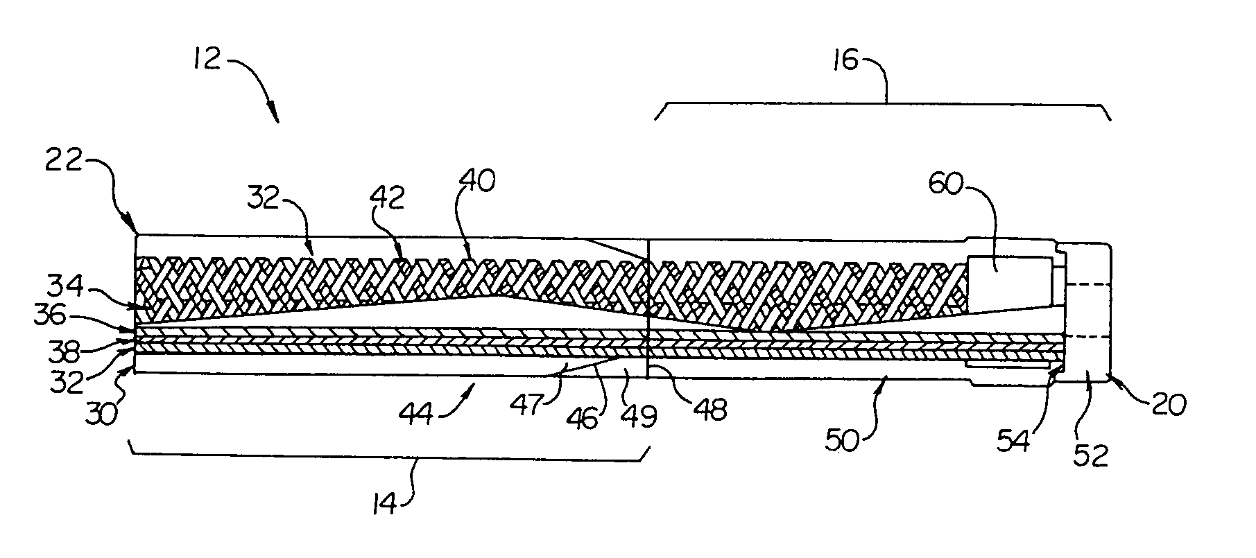
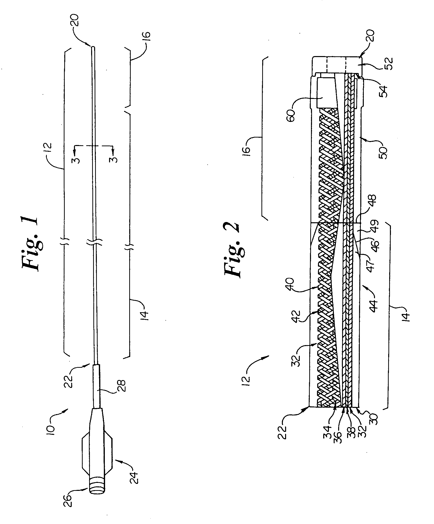
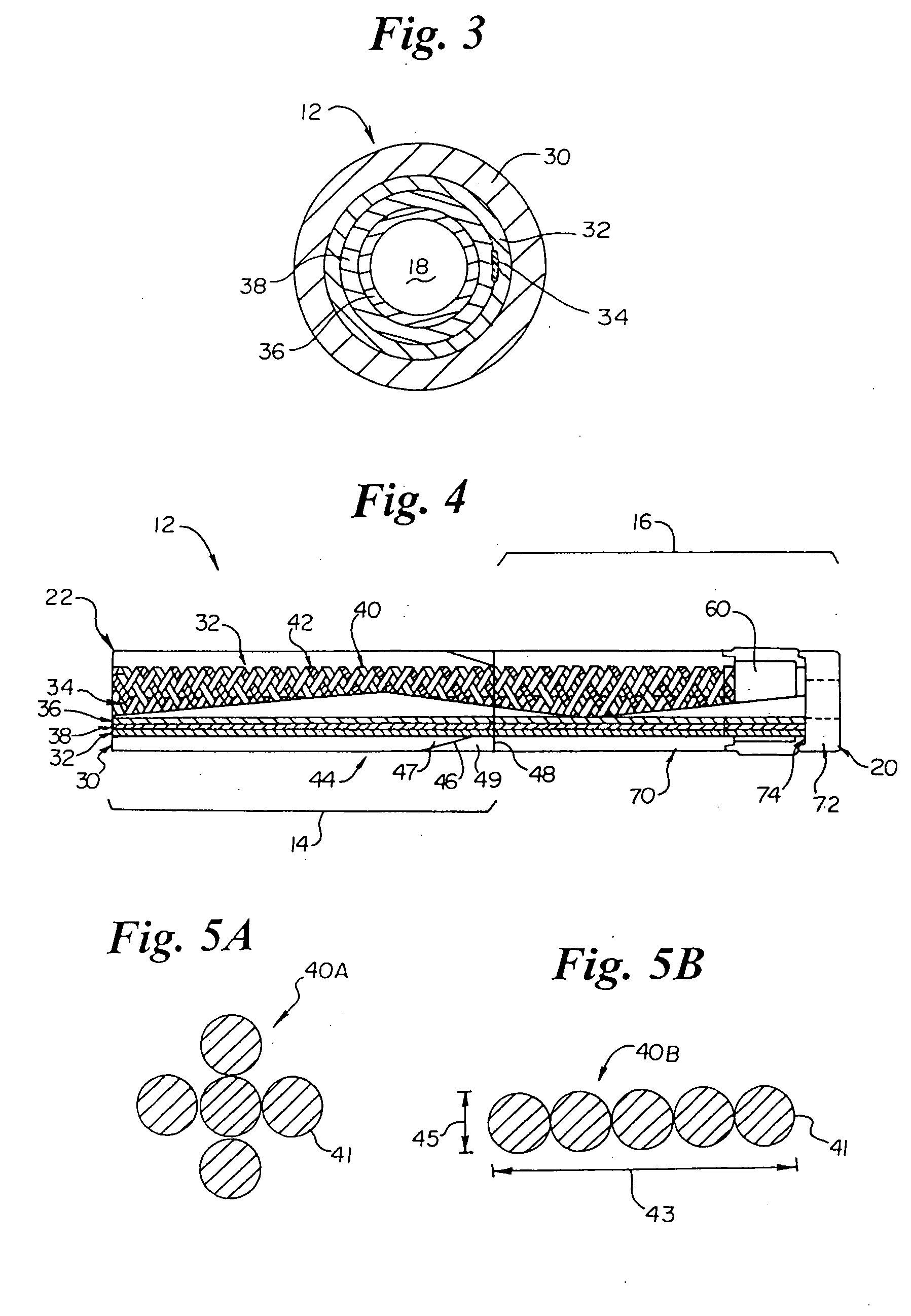
[0018]FIG. 1 illustrates intravascular catheter 10 in accordance with the present invention. Catheter 10 includes an elongate shaft 12 having a proximal region 14 and a distal region 16. The catheter 10 includes a lumen 18 (as best seen in FIG. 3) extending through the entire length of the elongate shaft 12 to an opening at the distal end 20 of the shaft 12. Catheter 10 may have a length of 80 to 150 cm and an outside diameter of approximately 3 F.

[0019] A manifold 24 is connected to the proximal end 22 of the shaft 12 which includes an interior (not visible) in fluid communication with the lumen 18 of the elongate shaft 12. Manifold 24 includes a standard fitting 26 for connection to a f...


PUM


Abstract

An intravascular catheter that exhibits the combined features of superior flexibility, softness, radiopacity and oval / kink resistance. The catheter includes an elongate shaft having a proximal region, a distal region and a lumen extending therethrough. The proximal region of the shaft includes an inner lubricious polymer layer, a reinforcement layer and an outer layer. The reinforcement layer comprises a braid having one or more metallic members and a plurality of polymer members wherein each polymer member comprises a plurality of monofilaments, preferably formed of LCP. The polymer members of the braid provide improved flexibility and softness in addition to high burst pressure. The metallic member(s) of the braid provide improved radiopacity and oval / kink resistance. The catheter may also include a longitudinal member extending along the reinforcement layer.

Description

CROSS REFERENCE TO RELATED APPLICATIONS [0001] This application is a continuation of co-pending U.S. application Ser. No. 10 / 339,055, filed Jan. 9, 2003; which is a continuation of U.S. application Ser. No. 09 / 684,819, filed Oct. 10, 2000, now U.S. Pat. No. 6,508,805; which is a continuation of U.S. application Ser. No. 09 / 234,203, filed Jan. 10, 1999, now U.S. Pat. No. 6,171,295, the disclosures of which are all incorporated herein by reference.BACKGROUND OF THE INVENTION [0002] The present invention generally relates to intravascular devices. More specifically, the present invention relates to reinforced intravascular catheters. [0003] Intravascular catheters are used in a wide variety of relatively non-invasive medical procedures. Such intravascular catheters may be used for diagnostic or therapeutic purposes. Generally, an intravascular catheter allows a physician to remotely perform a medical procedure by inserting the catheter into the vascular system of the patient at a locat...

Claims


Application Information

Patent Timeline
Patent Type & Authority Applications(United States)
IPC IPC(8): A61M25/00A61M25/16
CPCA61M25/0053A61M25/005
Inventor GARABEDIAN, ROBERT J.GRIEGO, JOHNBARDSLEY, EARLSCHAEFER, DEAN A.DAO, CANG D.ANDERSON, STEVEN M.
Owner BOSTON SCI SCIMED INC
Learn More