
Plenum cable

a plenum cable and cable technology, applied in the field of cables, can solve the problems of introducing safety hazards, affecting the safety of users, and affecting the safety of users, and achieve the effect of low-smoke generation and flame resistan

Inactive Publication Date: 2005-08-25
GENERAL CABLE TECH CORP
View PDF10 Cites 12 Cited by
  • Summary
  • Abstract
  • Description
  • Claims
  • Application Information

AI Technical Summary

Benefits of technology

[0012] It is an object of the present invention to provide an improved cable which is suitable for plenum applications and which is flame resistant and low-smoke generating.
[0015] A further object of the invention is to provide an improved plenum cable which is suitable for plenum applications and which can be efficiently and economically manufactured.
[0017] The present invention provides flame retardant and low-smoke cables using inexpensive materials. However, the inventive construction of the cables provides flame retardant and low-smoke characteristics without requiring expensive materials that are inherently flame retardant or contain flame retardant additive.

Problems solved by technology

Communications cables generally include voice communications, data and other types of signals for use in telephone, computer, control, alarm, and related systems, and it is not uncommon for these plenums and the cables therein to be continuous throughout the length and width of each floor, which can introduce safety hazards, both to the cables and the buildings.
However, if and when the fire reaches the plenum space, and especially if flammable material occupies the plenum, the fire can spread quickly throughout the entire floor of the building.
Also, smoke can be conveyed through the plenum to adjacent areas and to other floors with the possibility of smoke permeation throughout the entire building.
Afterwards, conductor insulation inside the jacket begins to decompose and char.
If the charred jacket retains its integrity, it still functions to insulate the core; if not, however, it ruptures due either to expanding insulation char or to pressure of gases generated from the insulation, and as a consequence, exposes the virgin interior of the jacket and insulation to the flame and / or the elevated temperatures.
These gases ignite and, because of air drafts in the plenum, burn beyond the area of flame impingement, thereby propagating flame and generating smoke and toxic and corrosive gases.
More particularly, it has become necessary to transmit data signals over considerable distances at high bit rates, such as megabits or gigabits per second, and to have substantially error free transmission.
However, the use of FMPE dielectric material and a PVC jacket generally does not result in a cable that satisfies UL 910.
However, those materials are generally expensive and / or in short supply, and thus are unsatisfactory from an economic standpoint, although outstanding for their flame and smoke retardation characteristics.
Both of those methods are also expensive and require specialized processing equipment.

Method used


Image

  • Plenum cable
  • Plenum cable

Examples


example

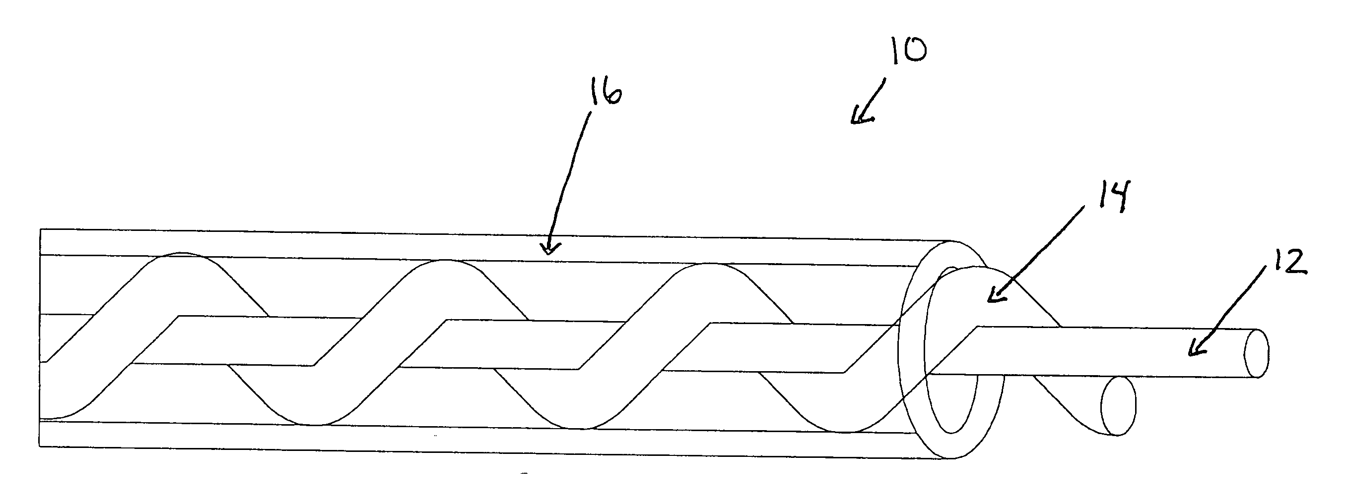
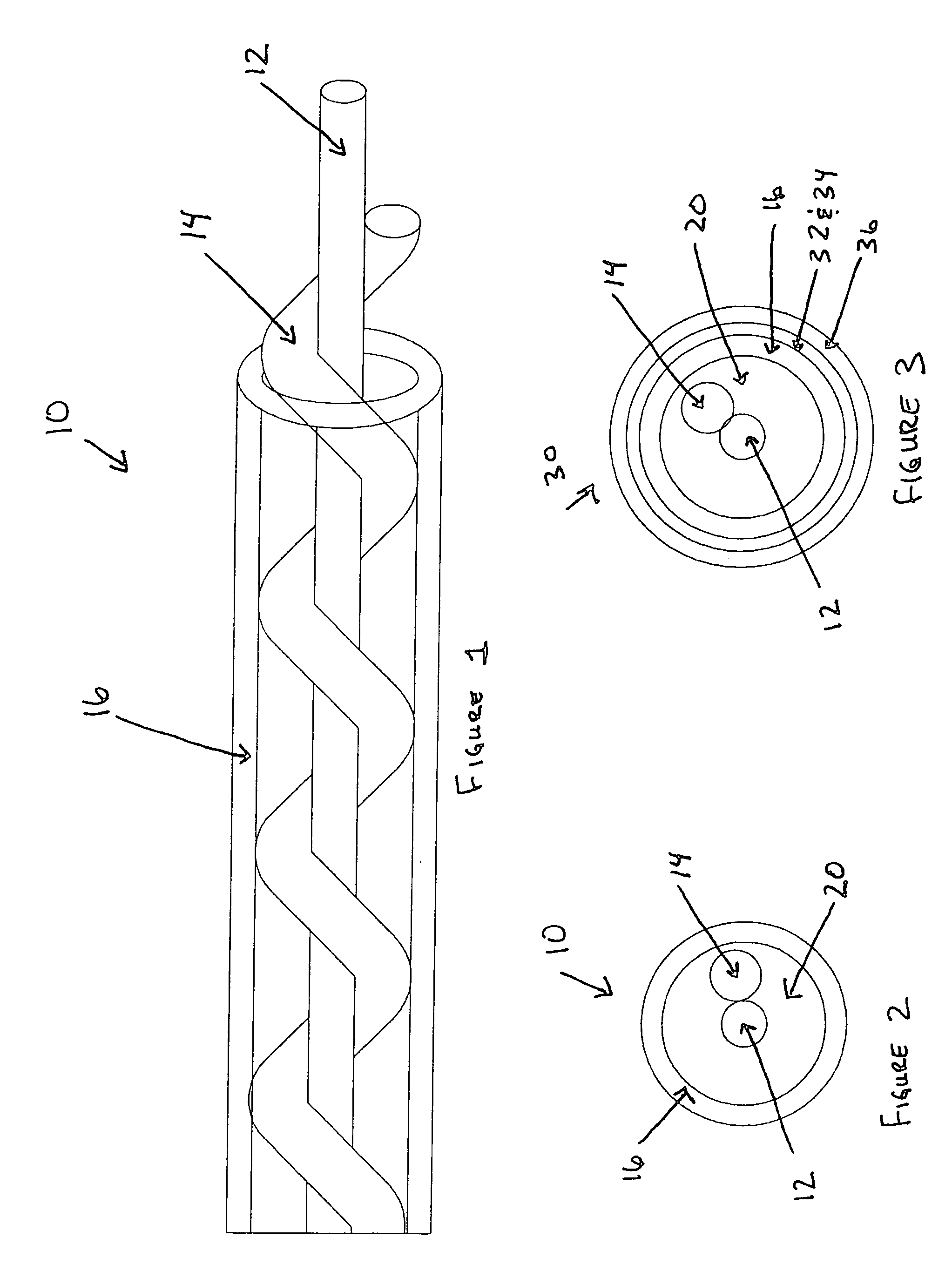
[0029] A coaxial cable was constructed in accordance with the Standard for Communications Cable, UL 444 / CSA-C22.2 No. 214. The conductor (No. 20 AWG or larger) was helically wrapped with a filament at a lay length of 0.6±0.2 in. The filament contained PVC extruded over a ripcord employing nylon, KEVLAR, polyester, or fiberglass, with a minimum thickness of 9 mils and a maximum average thickness of 15 mils. The insulator surrounding the filament-wrapped conductor was PVC with a minimum average thickness of 28 mils, minimum thickness of 25 mils, maximum average thickness of 39 mils, and a maximum overall tube diameter of 205 mils. The outer conductor comprised a shield and a braid. The shield consisted of metal, bimetal, aluminum / polyester or aluminum / polyester / aluminum tape which is 2±1 mils thick with a maximum overlap of 25%. The tape is applied longitudinally or helically over the cable core. The braid is tinned copper, bare copper or aluminum braid with 40% minumum coverage. The ...


PUM

PropertyMeasurementUnit
dielectric constantaaaaaaaaaa
thicknessaaaaaaaaaa

Abstract

The present invention relates to cables suitable for use in plenum applications, which exhibit flame spread and smoke generation properties that comply with industry standards, such as UL 910 or NFPA 262. The cable contains a conductor core that is wrapped with a filament in a spiral pattern along the length of the conductor. A dielectric is then extruded over the filament-wrapped conductor core to provide an insulated cable. To form a coaxial cable, a second conductor can also be provided on the outside of the dielectric and then covered with a jacket. The filament, dielectric, and jacket are preferably made of polyvinyl chloride (PVC).

Description

FIELD OF THE INVENTION [0001] The present invention relates generally to cables suitable for use in plenum applications. In particular, the present invention relates to coaxial cables suitable for use in plenum applications, which exhibit flame spread and smoke generation properties that comply with industry standards, e.g., UL 910 or NFPA 262. BACKGROUND OF THE INVENTION [0002] Buildings are usually designed with a space between a drop ceiling and a structural floor from which the ceiling is suspended to serve as a return air plenum for elements of heating and cooling systems as well as serving as a convenient location for the installation of communications cables and other equipment, such as power cables. Alternatively, the building can employ raised floors used for cable routing and plenum space. Communications cables generally include voice communications, data and other types of signals for use in telephone, computer, control, alarm, and related systems, and it is not uncommon ...

Claims


Application Information

Patent Timeline
Patent Type & Authority Applications(United States)
IPC IPC(8): H01B7/295H01B11/18
CPCH01B11/1847H01B7/295
Inventor HERBORT, TOM A.ROLAND, ALBEN D.
Owner GENERAL CABLE TECH CORP
Learn More