CMOS constant voltage generator

a constant voltage and generator technology, applied in the direction of electric variable regulation, process and machine control, instruments, etc., can solve the problems of unsuitable use in a number of important applications, and achieve the effect of reducing effective resistance values and resisting transistor values

Inactive Publication Date: 2005-08-25
ZMOS TECH
View PDF4 Cites 16 Cited by
  • Summary
  • Abstract
  • Description
  • Claims
  • Application Information

AI Technical Summary

Benefits of technology

[0025] Another aspect of the invention is that the resistance values of transistors can be controlled by changing their sizes (width and/or length), such as through blowing electri

Problems solved by technology

However, conventional CMOS Vref generators exhibit substantial operating voltage and temper

Method used


Image

  • CMOS constant voltage generator
  • CMOS constant voltage generator
  • CMOS constant voltage generator

Examples


Embodiment Construction

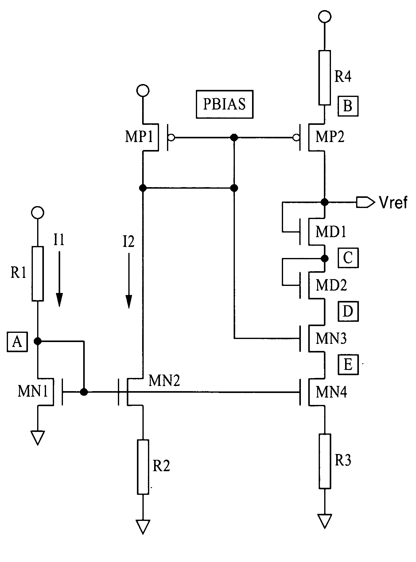
[0035] Referring more specifically to the drawings for illustrative purposes, the present invention is embodied in the apparatus generally described in FIG. 2 through FIG. 4. It will be appreciated that the apparatus may be adapted for a variety of applications, without departing from the basic concepts disclosed herein. The present invention is a new type of CMOS voltage reference (Vref) generator which is directed toward achieving superior compensation performance (i.e., reduced sensitivity to supply voltage (Vdd) and temperature variations) in relation with conventional CMOS Vref generators. The apparatus and methods of the present invention can be implemented within separate circuit elements (i.e. voltage references, regulators, etc.) or integrated within other circuit elements, preferably those fabricated using CMOS processes (i.e. A / D converters, microcontrollers, comparator circuits and so forth).

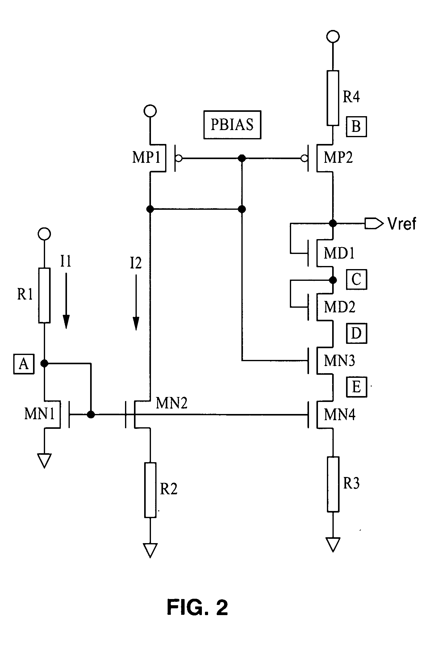
[0036]FIG. 2 illustrates an example embodiment of a CMOS Vref generator accordi...


PUM


Abstract

A CMOS constant voltage generator circuit having input and output stages and at least one compensation stage. Each stage can comprise a single transistor or more typically a transistor stack. Current mirroring is performed between the input stage and compensation stage, as well as preferably between the input stage and output stage. The compensation stage also provides additional biasing to a transistor in the output stage to increase voltage regulation. Optionally, degeneration resistors (passive or active) are coupled to the source side, drain side, or a combination of source and drain sides in the compensation and output stages. Optionally, additional diode-coupled transistors are incorporated in the transistor stack of the output stage. The circuit provides accurate voltage reference (Vref) output with lowered sensitivity to temperature and supply voltage.

Description

CROSS-REFERENCE TO RELATED APPLICATIONS [0001] This application claims priority from U.S. provisional application Ser. No. 60 / 539,051 filed on Jan. 23, 2004, incorporated herein by reference in its entirety.STATEMENT REGARDING FEDERALLY SPONSORED RESEARCH OR DEVELOPMENT [0002] Not Applicable INCORPORATION-BY-REFERENCE OF MATERIAL SUBMITTED ON A COMPACT DISC [0003] Not Applicable NOTICE OF MATERIAL SUBJECT TO COPYRIGHT PROTECTION [0004] A portion of the material in this patent document is subject to copyright protection under the copyright laws of the United States and of other countries. The owner of the copyright rights has no objection to the facsimile reproduction by anyone of the patent document or the patent disclosure, as it appears in the United States Patent and Trademark Office publicly available file or records, but otherwise reserves all copyright rights whatsoever. The copyright owner does not hereby waive any of its rights to have this patent document maintained in secr...

Claims


Application Information

Patent Timeline
IPC IPC(8): G05F1/10
CPCG05F3/247G05F1/10
Inventor CHOI, MYUNG CHAN
Owner ZMOS TECH
Why Eureka
Try Eureka