
Method and apparatus for constant linear velocity electron beam substrate processing

a technology of electron beam substrate and processing method, which is applied in the field of processing substrates with electron beams, can solve the problems of reducing the processing throughput of substrates used in increasing the cost and complicated reconfiguration of electron beam substrate processing systems to process substrates used in both cav and clv systems

Inactive Publication Date: 2005-08-25
SEAGATE TECH LLC
View PDF3 Cites 11 Cited by
  • Summary
  • Abstract
  • Description
  • Claims
  • Application Information

AI Technical Summary

Benefits of technology

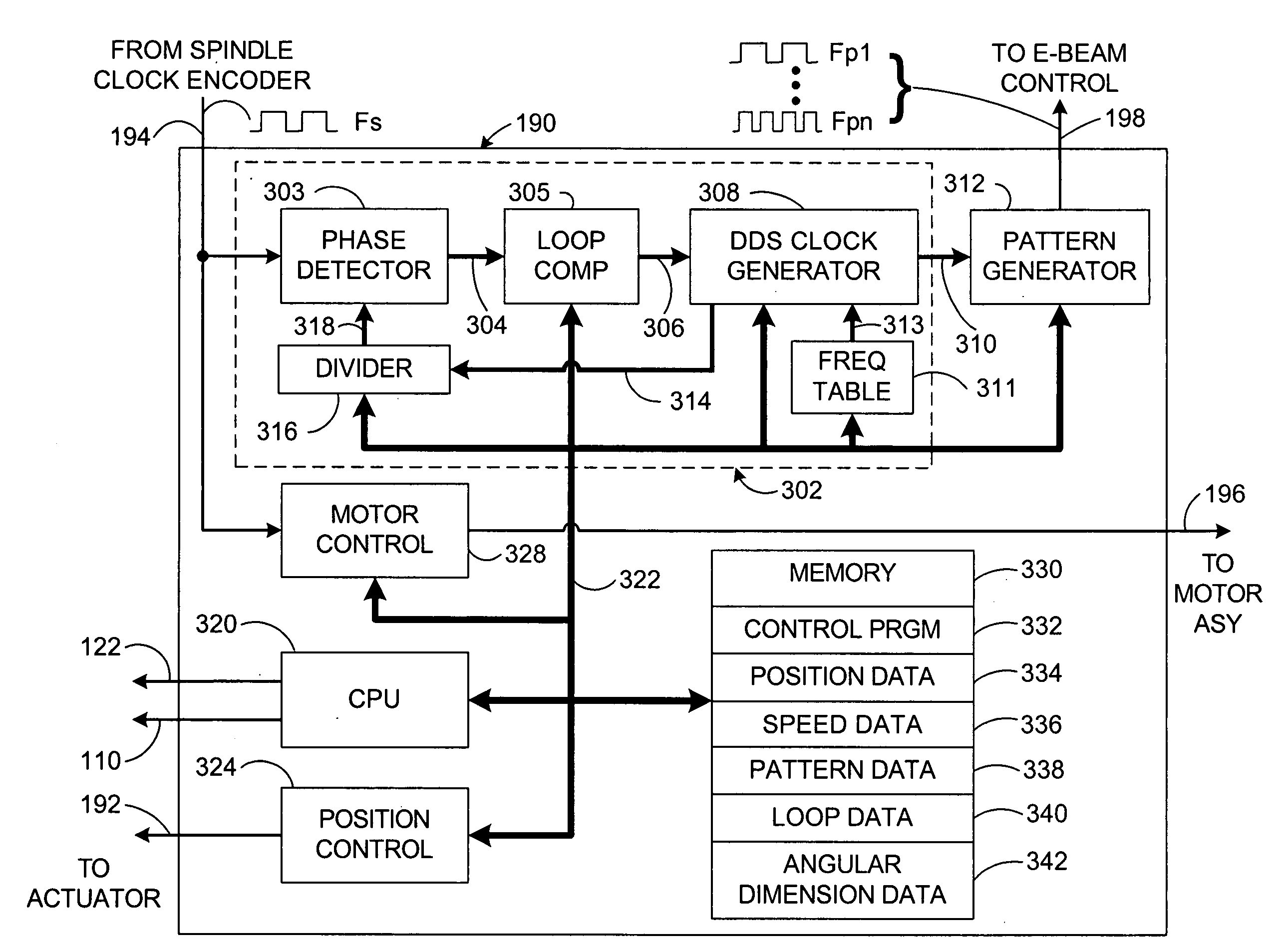
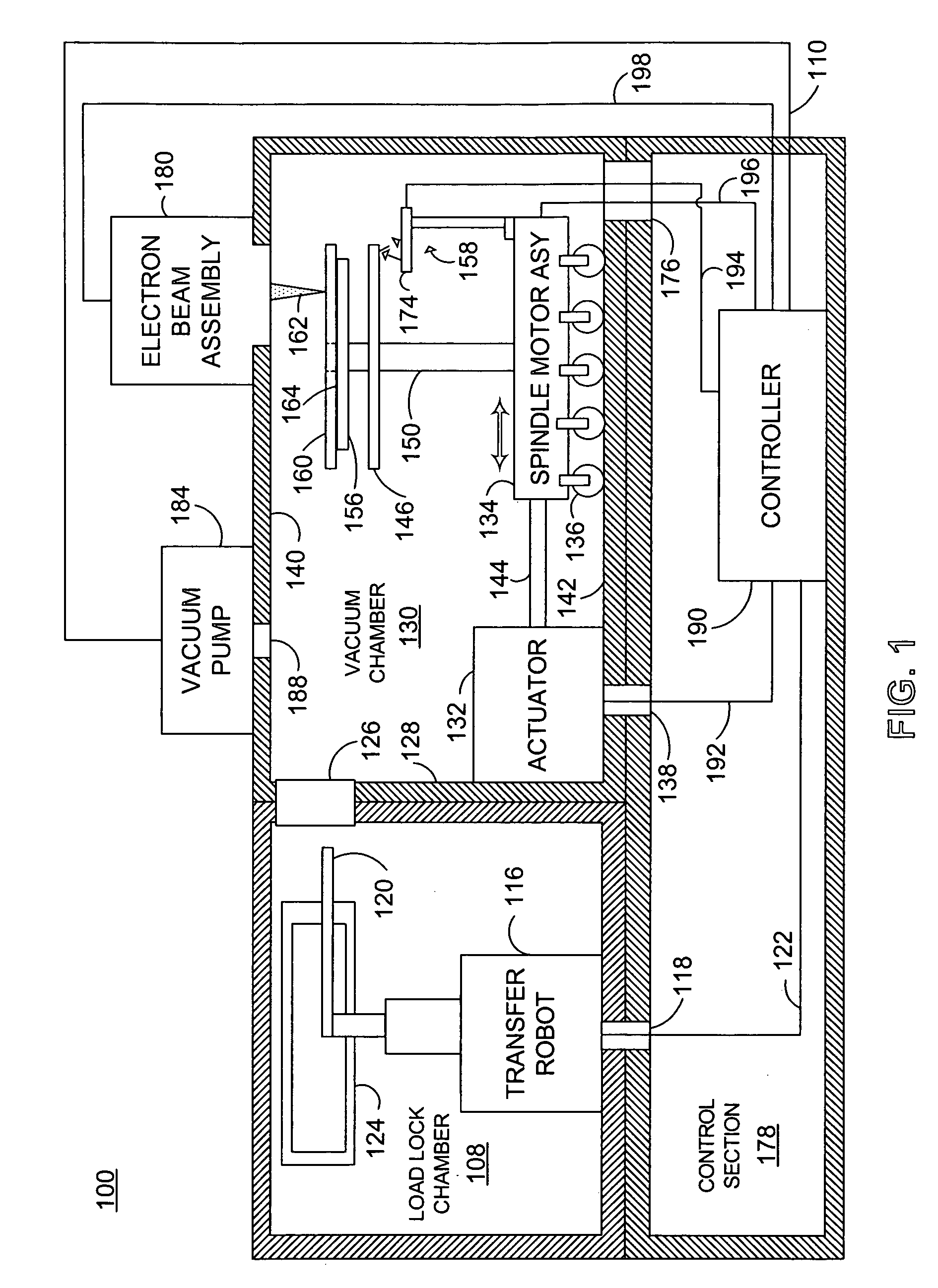
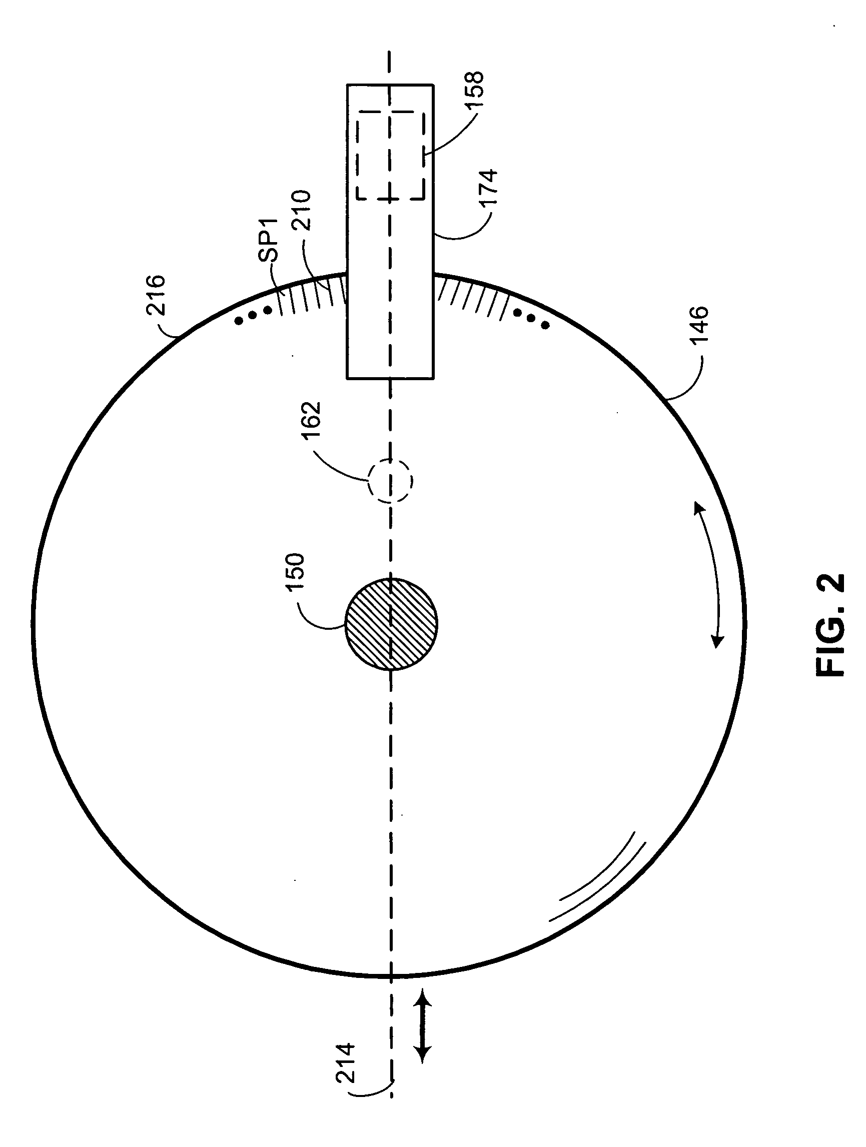
[0012] An aspect of the present invention generally provides an electron beam substrate processing apparatus. The apparatus includes a substrate processing chamber defined by sidewalls, a bottom, and a top, a spindle motor assembly moveably disposed within the substrate processing chamber, and a spindle shaft extending from the spindle motor assembly toward the top. A substrate support member is mounted to an end of the spindle shaft distal the spindle motor assembly. An encoder wheel coupled to the spindle shaft is positioned adjacent the substrate support member. An optical detector is positioned in optical communication with the encoder wheel. T

Problems solved by technology

Unfortunately, reconfiguring electron beam substrate processing systems to process substrates used for both CAV and CLV systems is generally complicated, prone to configuration errors, and is time consuming which reduces substrate processing throughput.
Conventionally, to solve this issue, manufactures often use separate electron beam substrate processing systems optimized for processing substrates for either CLV or CAV systems, which generally increases the cost of electron beam substrate processing.

Method used


Image

  • Method and apparatus for constant linear velocity electron beam substrate processing
  • Method and apparatus for constant linear velocity electron beam substrate processing
  • Method and apparatus for constant linear velocity electron beam substrate processing

Examples


Embodiment Construction

[0022] In the following description, numerous specific details are set forth to provide a more thorough understanding of the present invention. However, it will be apparent to one of skill in the art that the present invention may be practiced without one or more of these specific details. In other instances, well-known features have not been described in order to avoid obscuring the present invention.

[0023] As will be described below, aspects of one embodiment pertain to specific method steps implementable on computer systems. In one embodiment, the invention may be implemented as a computer program-product for use with a computer system. The programs defining the functions of at least one embodiment can be provided to a computer via a variety of computer-readable media (i.e., signal-bearing medium), which include but are not limited to, (i) information permanently stored on non-writable storage media (e.g. read-only memory devices within a computer such as read only CD-ROM disks ...


PUM


Abstract

Embodiments of the invention generally provide an electron beam substrate processing system. In one embodiment, the present invention provides an electron beam substrate processing system where a spindle shaft used to rotate substrates during processing includes at least one optical encoder wheel assembly. The optical encoder wheel assembly is configured to provide rotational speed data signal to a rotational speed control system and a pattern generation clock circuit configured to a provide an angular pattern generator clock signal and to a pattern generator circuit. The pattern generation circuit is configured to control modulation of an electron beam used for substrate processing. In one aspect of the present invention, while the spindle shaft is rotated at a constant linear velocity, the pattern generation circuit controls the modulation of an electron beam such that written mark lengths are sized to be about constant in angular dimension.

Description

BACKGROUND OF THE INVENTION [0001] 1. Field of the Invention [0002] The invention relates generally to processing substrates with electron beams. More particularly, the present invention relates to applying electron beams to surfaces of substrates to write data patterns thereon. [0003] 2. Description of the Related Art [0004] In electron beam substrate processing systems, a narrowly converged electron beam is applied to target positions on the surface of substrates to form patterns thereon. Electron beam substrate processing systems generally include an electron gun, electromagnetic lens, and a vacuum chamber for holding the specimen substrate. Electron beam substrate processing systems write a desired pattern on a substrate surface usually coated with electron beam resist by focusing, directing, and blanking the electron beam such that only specified surface areas of the substrate are processed. [0005] Processing substrates generally involves raster-scan and vector-scan processes. ...

Claims


Application Information

Patent Timeline
IPC IPC(8): G11B9/10H01J37/302
CPCG11B5/8404G11B7/26H01J2237/31735H01J37/3023G11B9/10
Inventor CHAUHAN, SUNDEEPBRYANT, LAWRENCEDEEMAN, NEILFORMATO, CHRISTOPHERKUO, DAVID
Owner SEAGATE TECH LLC
Learn More