
DMA controller having programmable channel priority

a controller and channel technology, applied in the field of digital processing systems, can solve the problems of high interrupt rate, time operation, intensive numeric computation, etc., and achieve the effect of reducing the number of interrupts, and improving the efficiency of the dma controller

Active Publication Date: 2005-08-25
ANALOG DEVICES INC
View PDF5 Cites 6 Cited by
  • Summary
  • Abstract
  • Description
  • Claims
  • Application Information

AI Technical Summary

Benefits of technology

[0010] According to a first aspect of the invention, a DMA controller is provided. The DMA controller comprises a plurality of DMA channels, each including a datapath for transferring data from a DMA source to DMA destination and

Problems solved by technology

Digital signal processors are typically characterized by real time operation, high interrupt rates and intensive numeric computations.
In addition, digital signal processor applications tend to be intensive in memory access operations and to require the input and output of large quantities of data.
A disadvantage of such implementations is that the sum of the lengths of the pipeline for access to DMA resources and the pipeline for access to memory represents overhead.
Such implementations often mitigate this overhead by adding the complexity of DMA bus bursts under hardware or software control.
For a first example, a prior art DMA controller uses a single DMA memory access bus with a single pipeline for all memory accesses; this implementation cannot support independent fast accesses to internal memory and slow accesses to external memory at the same time.
This implementation does not support unrestricted operation where the source may be either internal or external and the destination may independently be internal or external.
Such implementations cannot dynamically respond to transitory real-time transfer demands caused by congestion delays, and therefore the system designer must reduce the overall system DMA bandwidth budget (and hence system performance) to eliminate the risk of momentary DMA failure.
All of the prior art DMA controllers have had one or more drawbacks, including but not limited to high latency in servicing DMA requests and excessive complexity.

Method used


Image

  • DMA controller having programmable channel priority
  • DMA controller having programmable channel priority
  • DMA controller having programmable channel priority

Examples


Embodiment Construction

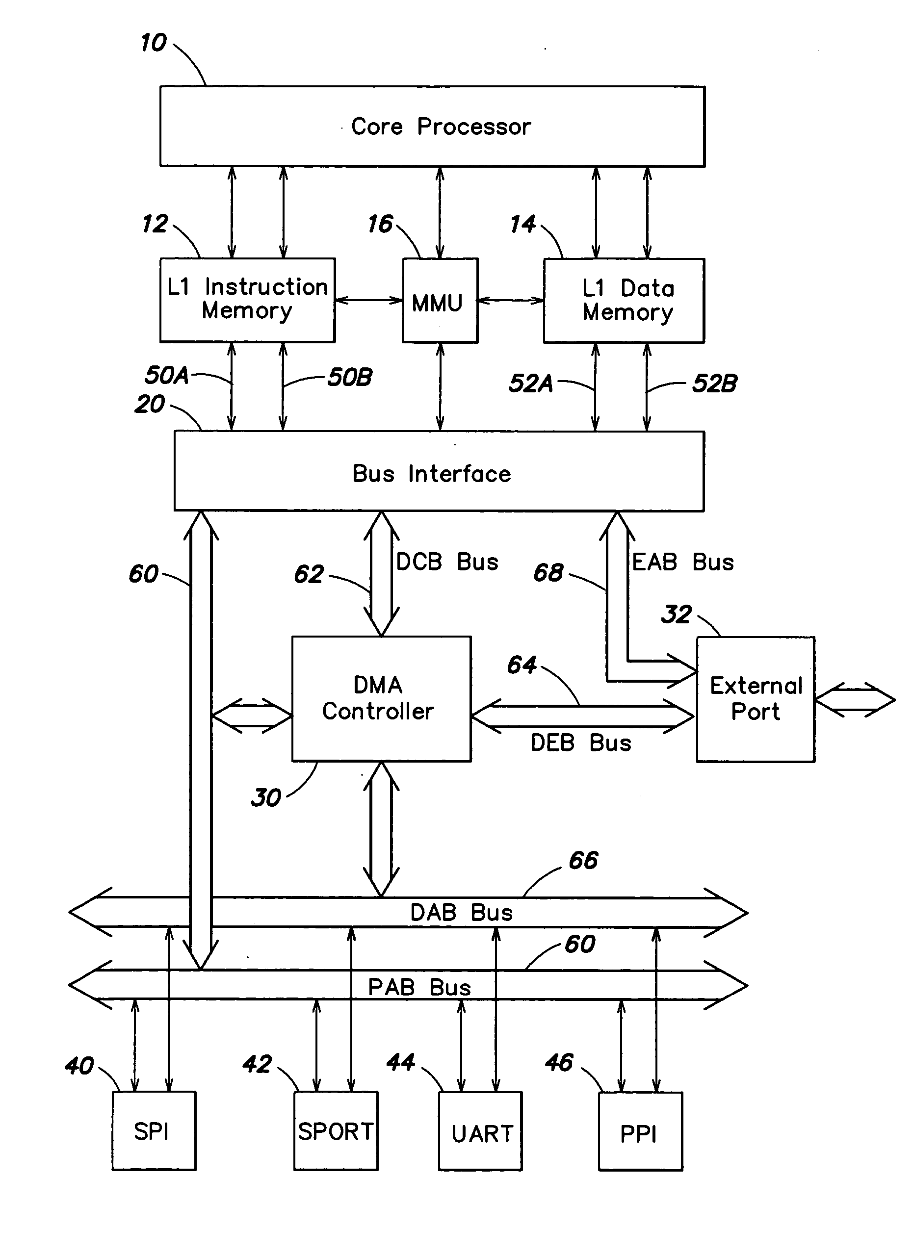
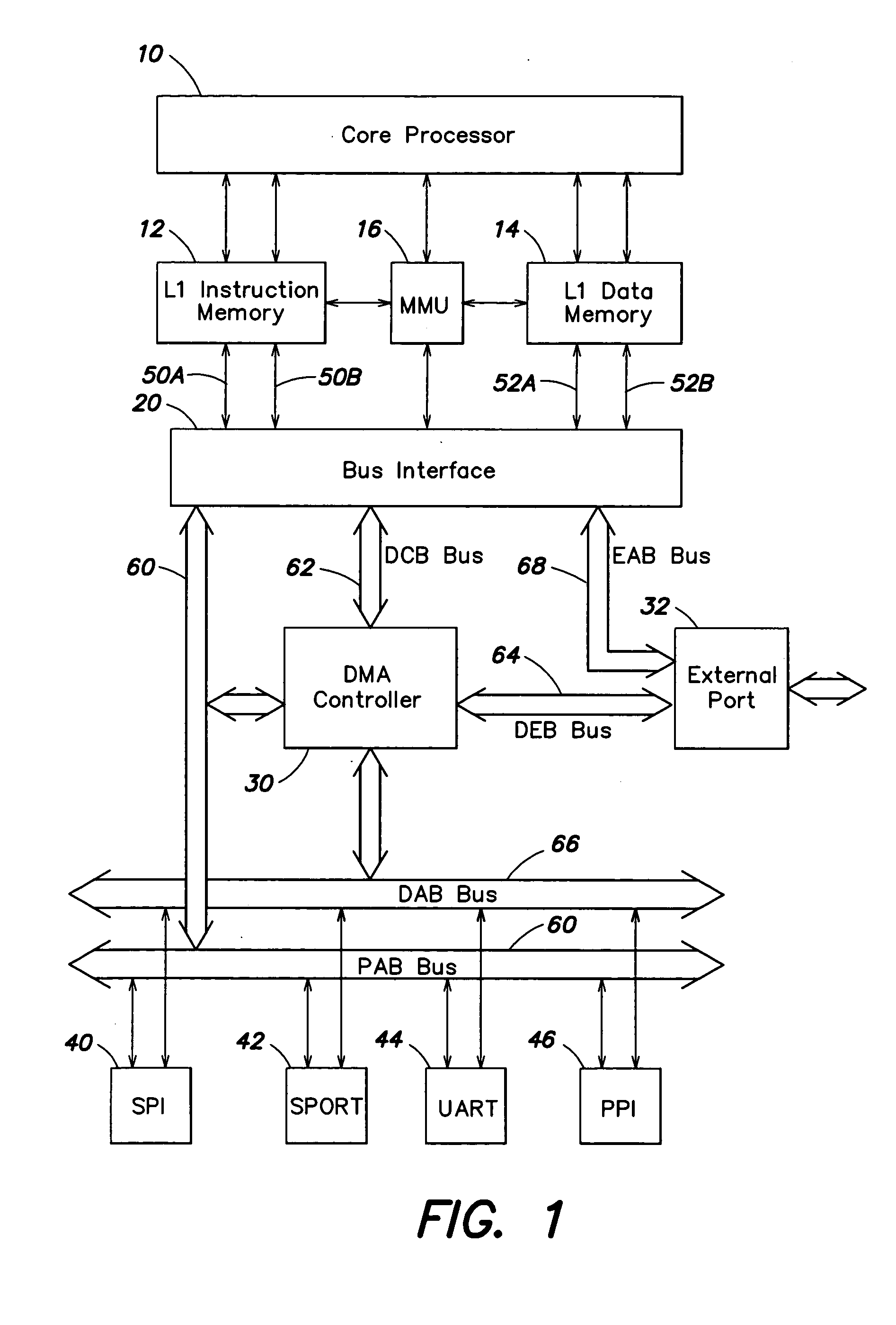
[0025] A block diagram of a digital signal processor in accordance with an embodiment of the invention is shown in FIG. 1. The digital signal processor (DSP) includes a core processor 10, a level 1 (L1) instruction memory 12, an L1 data memory 14, a memory management unit (MMU) 16 and a bus interface unit 20. In some embodiments, L1 instruction memory 12 may be configured as RAM or as instruction cache and L1 data memory 14 may be configured as RAM or as data cache. The DSP further includes a DMA controller 30, an external port 32 and one or more peripheral ports. In the embodiment of FIG. 1, the DSP includes a serial peripheral interface (SPI) port 40, a serial port (SPORT) 42, a UART port 44 and a parallel peripheral interface (PPI) port 46. The digital signal processor may include additional peripheral ports and other components within the scope of the invention. For example, the digital signal processor may include on-chip L2 memory.

[0026] Bus interface unit 20 is connected to ...


PUM


Abstract

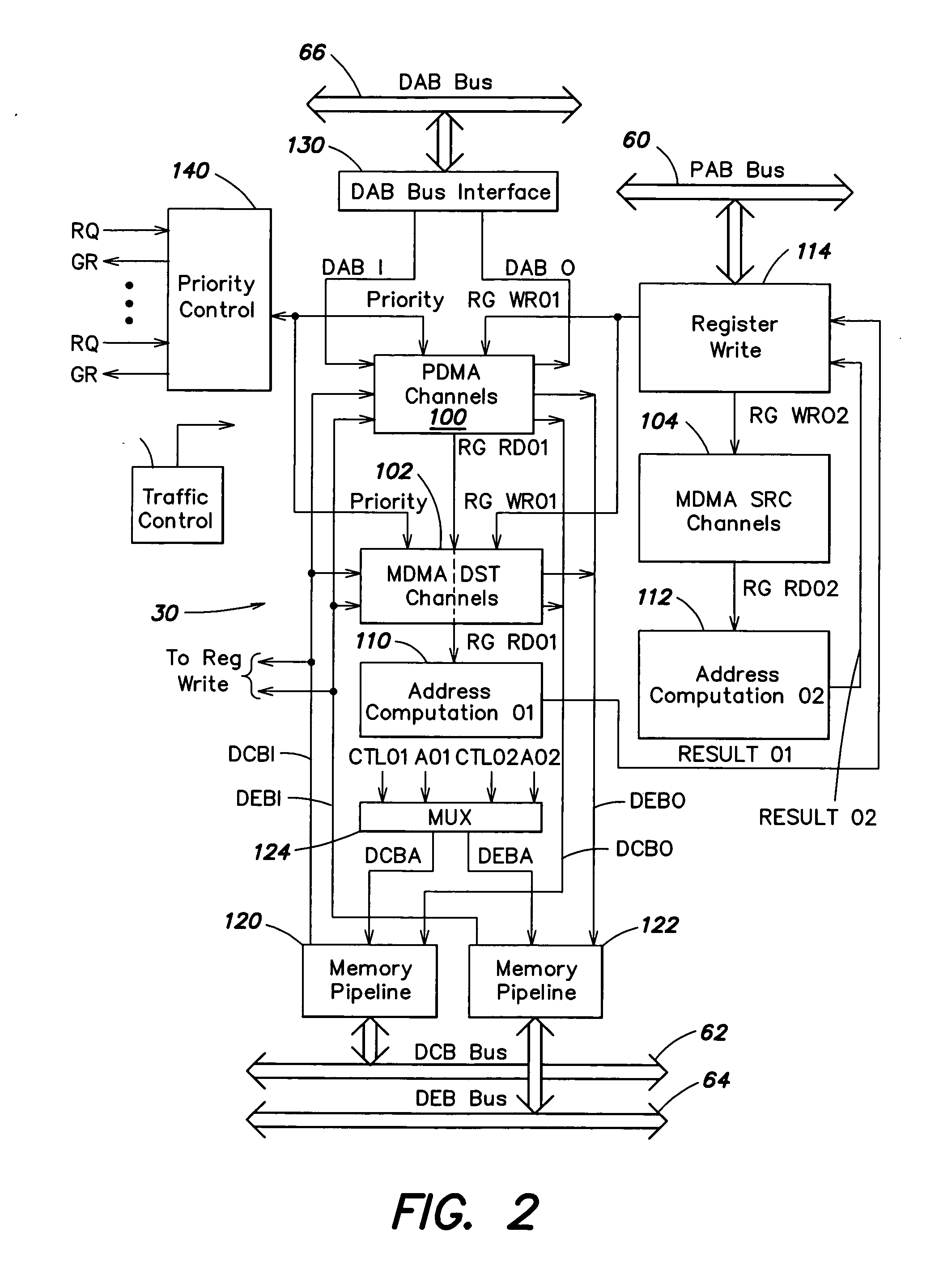
A DMA controller includes at least one peripheral DMA channel for handling DMA transfers on a peripheral access bus; at least one memory DMA stream, including a memory destination channel and a memory source channel, for handling DMA transfers on first and second memory access buses; first and second address computation units for computing updated memory addresses for DMA transfers; and first and second memory pipelines for supplying memory addresses to the first and second memory access buses, respectively, and for transferring data on the first and second memory access buses. The DMA controller further includes a prioritizer configured to map DMA requests from different DMA requesters to the peripheral channels in response to programmable mapping information.

Description

FIELD OF THE INVENTION [0001] This invention relates to digital processing systems and, more particularly, to methods and apparatus for direct memory access (DMA) in digital processing systems. The DMA methods and apparatus are particularly useful in digital signal processors, but are not limited to such applications. BACKGROUND OF THE INVENTION [0002] A digital signal computer, or digital signal processor (DSP), is a special purpose computer that is designed to optimize performance for digital signal processing applications, such as, for example, fast Fourier transforms, digital filters, image processing, signal processing in wireless systems, and speech recognition. Digital signal processors are typically characterized by real time operation, high interrupt rates and intensive numeric computations. In addition, digital signal processor applications tend to be intensive in memory access operations and to require the input and output of large quantities of data. Digital signal proce...

Claims


Application Information

Patent Timeline
IPC IPC(8): G06F13/28G06F13/34
CPCG06F13/34
Inventor HAYDEN, JOHN A.KOKER, GREGORY T.
Owner ANALOG DEVICES INC
Learn More