Reformer and process for reacting fuel and oxidizer into reformate

Inactive Publication Date: 2005-09-01
EHNERDEJ GMBKH
View PDF9 Cites 4 Cited by
  • Summary
  • Abstract
  • Description
  • Claims
  • Application Information

AI Technical Summary

Benefits of technology

[0014] A primary object of the invention is to provide a reformer and a process for reaction of fuel and oxidizer so that components are not damaged; and which, in addition, will make it possible to easily and reliably influence the reforming process, especially reforming using the process of partial oxidation (POX).

Problems solved by technology

The disadvantage in this catalytic reforming is the large amount of heat which is produced and which can irreversibly damage the system components, especially the catalyst.
Here, however, there are the additional disadvantages that a supply possibility for water must be made available.
High temperature gradients between the oxidation zone and the reforming zone represent other problems in the temperature economy of the entire system.
This can lead to damage of the materials involved, for example, of the catalyst.
Thus, the hot-spot, depending on the fuel output, can be located at different points of the oxidation zone; this increases the potentially damaged area of the reaction zone.
Other problems are associated with the fact that, for low output, most of the exothermal chemical reactions are concentrated at the input area of the reaction zone.
This can lead to the product gas temperature at the exit from the reformer being too low, especially for continued processing of the reformate in a fuel cell.
Other problems resulting from the temperature drop in the reaction zone are associated with the fact that, due to the low temperatures in the reforming zone located downstream of the oxidation zone, hydrocarbon emissions are high due to the low fuel conversions, and the tendency of the catalyst to coking and poisoning is increased.
As a result, a downstream fuel cell cannot produce electrical energy during this time.

Method used


Image

  • Reformer and process for reacting fuel and oxidizer into reformate
  • Reformer and process for reacting fuel and oxidizer into reformate
  • Reformer and process for reacting fuel and oxidizer into reformate

Examples


Embodiment Construction

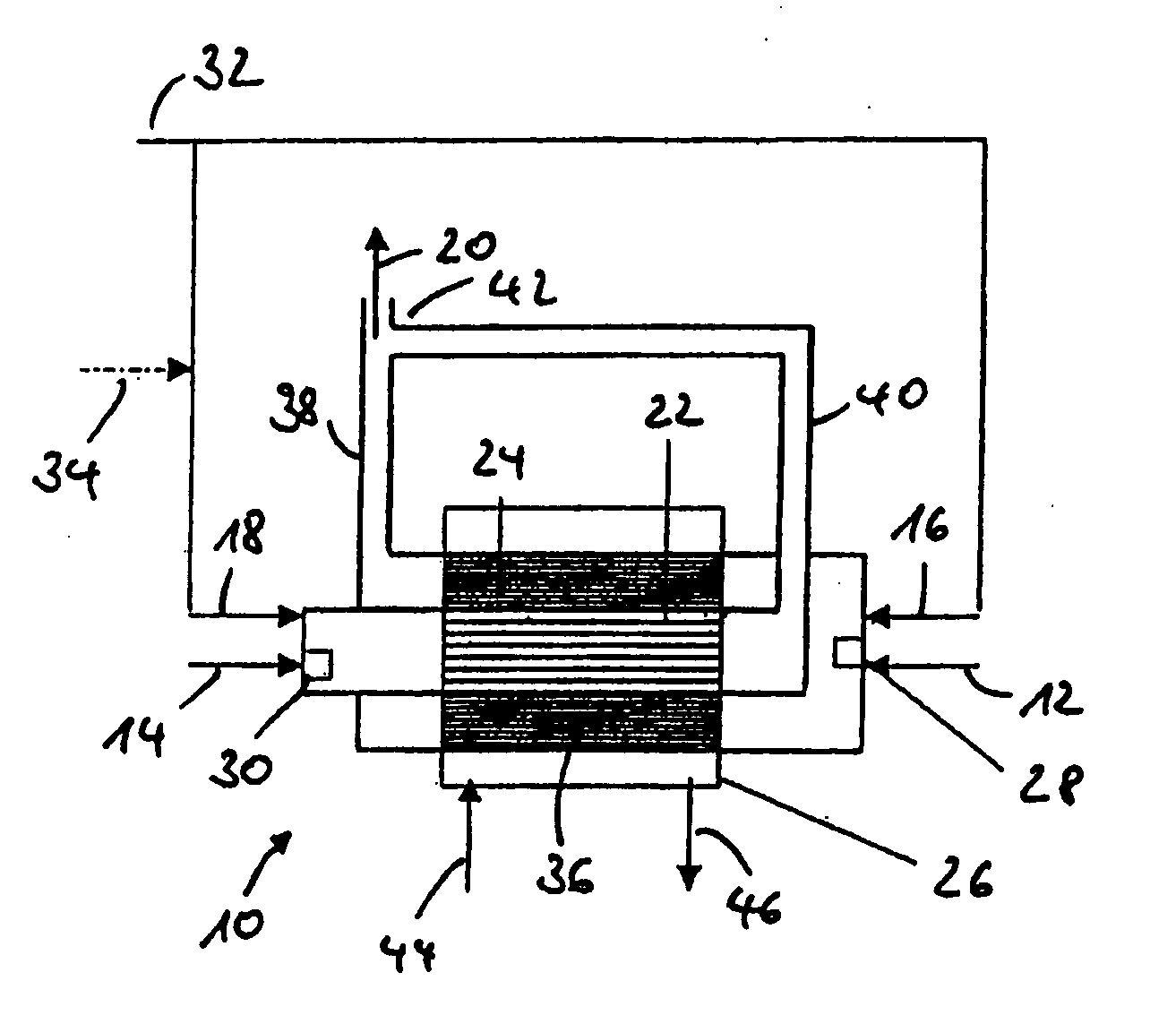
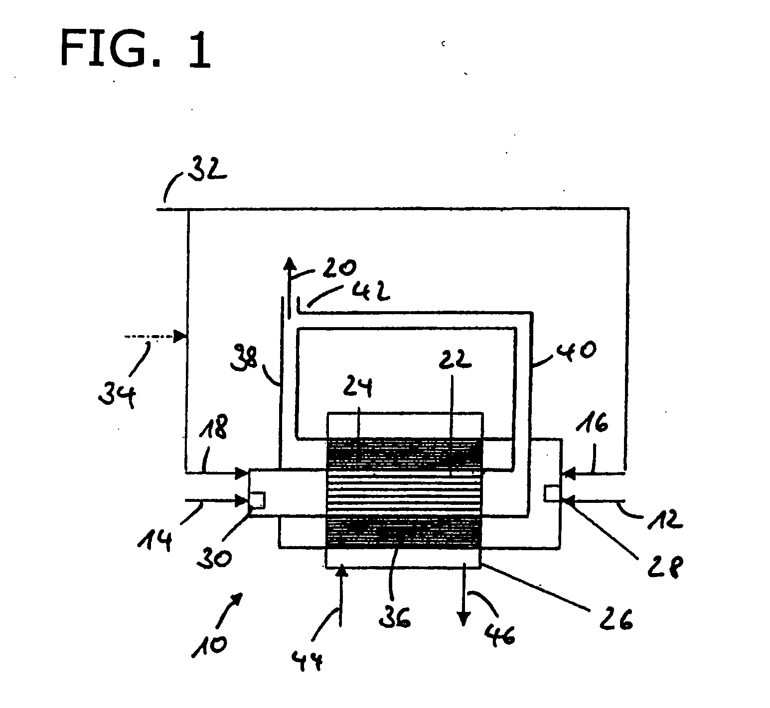
[0033]FIG. 1 shows a schematic of a reformer 10 in accordance with the invention that has two reaction zones 22, 24. The reaction zones 22, 24 are made essentially axially symmetrical, one reaction zone 24 surrounding the other reaction zone 22. At the input of each of the reaction zones 22, 24, there is an injection system 28, 30 for injection of fuel 12, 14 into the reaction zones 22, 24.

[0034] Furthermore, oxidizer 16, 18, i.e., especially air, can be supplied to the reaction zones 22, 24. For this purpose, there can be separate air supplies, or as in this example, there can be a central air supply 32, and one or more valves 34 can be provided to vary the amounts of air which are supplied to the respective reaction zones 22, 24. Within the reaction zones 22, 24, there is a catalyst 36 or several catalysts so that a reforming process can be carried out using the principle of catalytic partial oxidation (CPOX). Additionally, there are product gas guides 38, 40 which lead to a mixi...


PUM


Abstract

A reformer (10) for reacting fuel (12, 14) and oxidizer (16, 18) into reformate (20), with a plurality of reaction zones (22, 24) to which the fuel (12) and oxidizer (16) are supplied and in each which the fuel and oxidizer are reacted into reformate. The process for reacting fuel and oxidizer into reformate separately adjusting the fuel and / or oxidizer supplied to the reaction zones for varying the reformate output produced.

Description

BACKGROUND OF THE INVENTION [0001] 1. Field of Invention [0002] The invention relates to a reformer for reacting fuel and oxidizer into reformate, with a reaction zone to which the fuel and oxidizer can be supplied. [0003] The invention relates furthermore to a process for reacting fuel and oxidizer into reformate in a reformer with a reaction zone, in which fuel and oxidizer are supplied to the reaction zone. [0004] 2. Description of Related Art [0005] Generic reformers and generic processes have numerous applications. In particular, they are used to supply a hydrogen-rich gas mixture to a fuel cell, from which, then, based on electrochemical processes, electrical energy can be produced. These fuel cells are used, for example, in the motor vehicle art as auxiliary energy sources, for example, APUs (“auxiliary power units”). [0006] The design of the reformer is dependent on many factors. In addition to taking into account the properties of the reaction system, for example, economic ...

Claims


Application Information

Patent Timeline
IPC IPC(8): B01J8/04B01J12/00C01B3/36C01B3/38
CPCB01J8/0496C01B2203/82B01J2208/00309B01J2208/0053C01B3/36C01B3/382C01B3/384C01B3/386C01B2203/0255C01B2203/0261C01B2203/066C01B2203/0844C01B2203/0883C01B2203/1247C01B2203/141C01B2203/169B01J12/007
Inventor KAH, STEFANJAHN, MATTHIASMUEHLNER, MARCOLINDERMEIR, ANDREASKAVURUCU, SENA
Owner EHNERDEJ GMBKH
Why Eureka
Try Eureka