Angular velocity sensor

Inactive Publication Date: 2005-09-01
SONY CORP
View PDF7 Cites 11 Cited by
  • Summary
  • Abstract
  • Description
  • Claims
  • Application Information

AI Technical Summary

Benefits of technology

[0017] The present invention has been made in view of the foregoing. An object of this invention is to provide a vibration gyro-typ

Problems solved by technology

Further, since the silver or gold coating inherently has low resistance and chemically stable, its oxidation or

Method used


Image

  • Angular velocity sensor
  • Angular velocity sensor
  • Angular velocity sensor

Examples


Embodiment Construction

[0042] An embodiment of the present invention will be described in detail, with reference to the accompanying drawings. Nonetheless, the invention is not limited to the embodiment. Various changes and modifications can of course be made within the scope and spirit of the present invention.

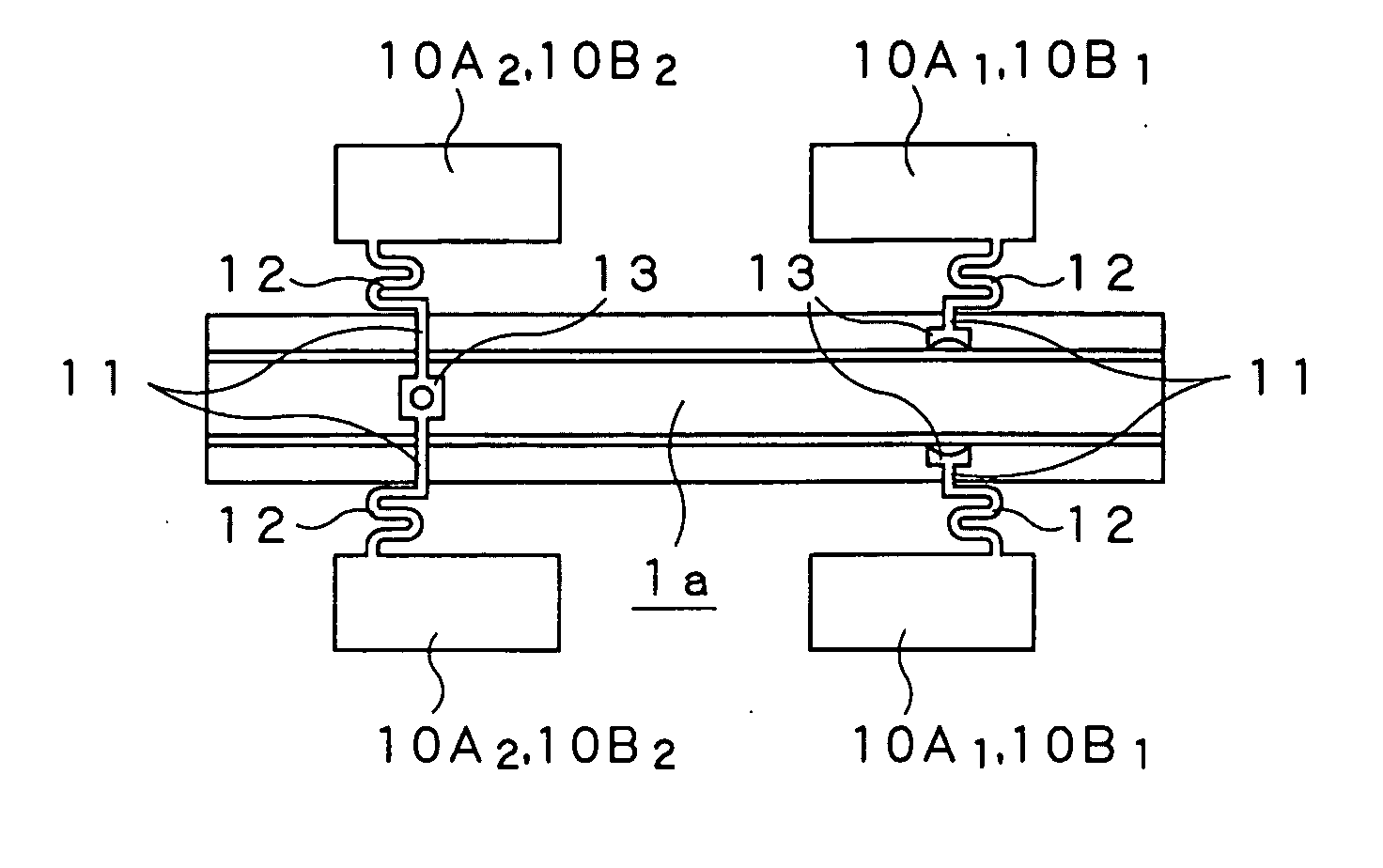
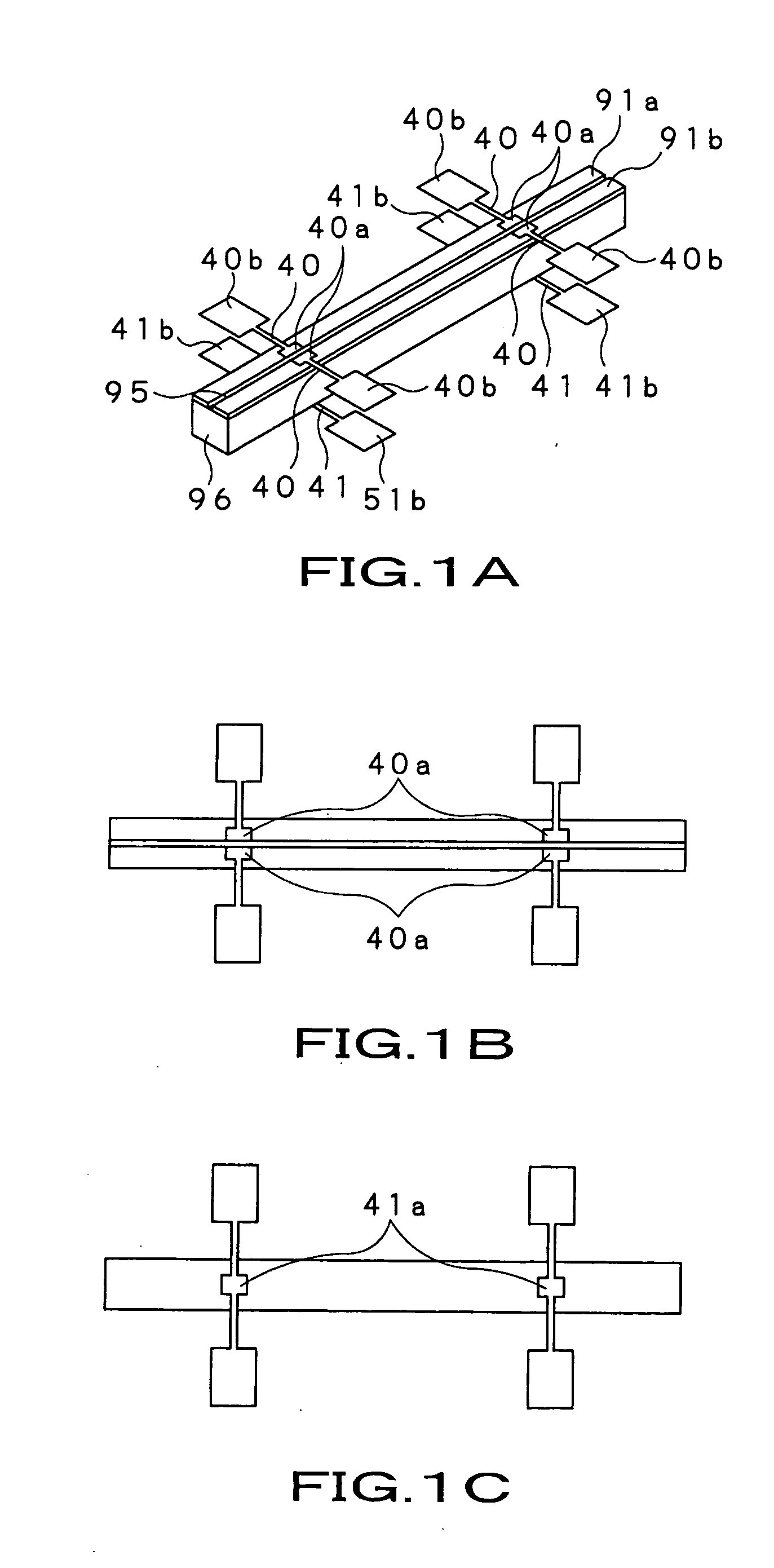
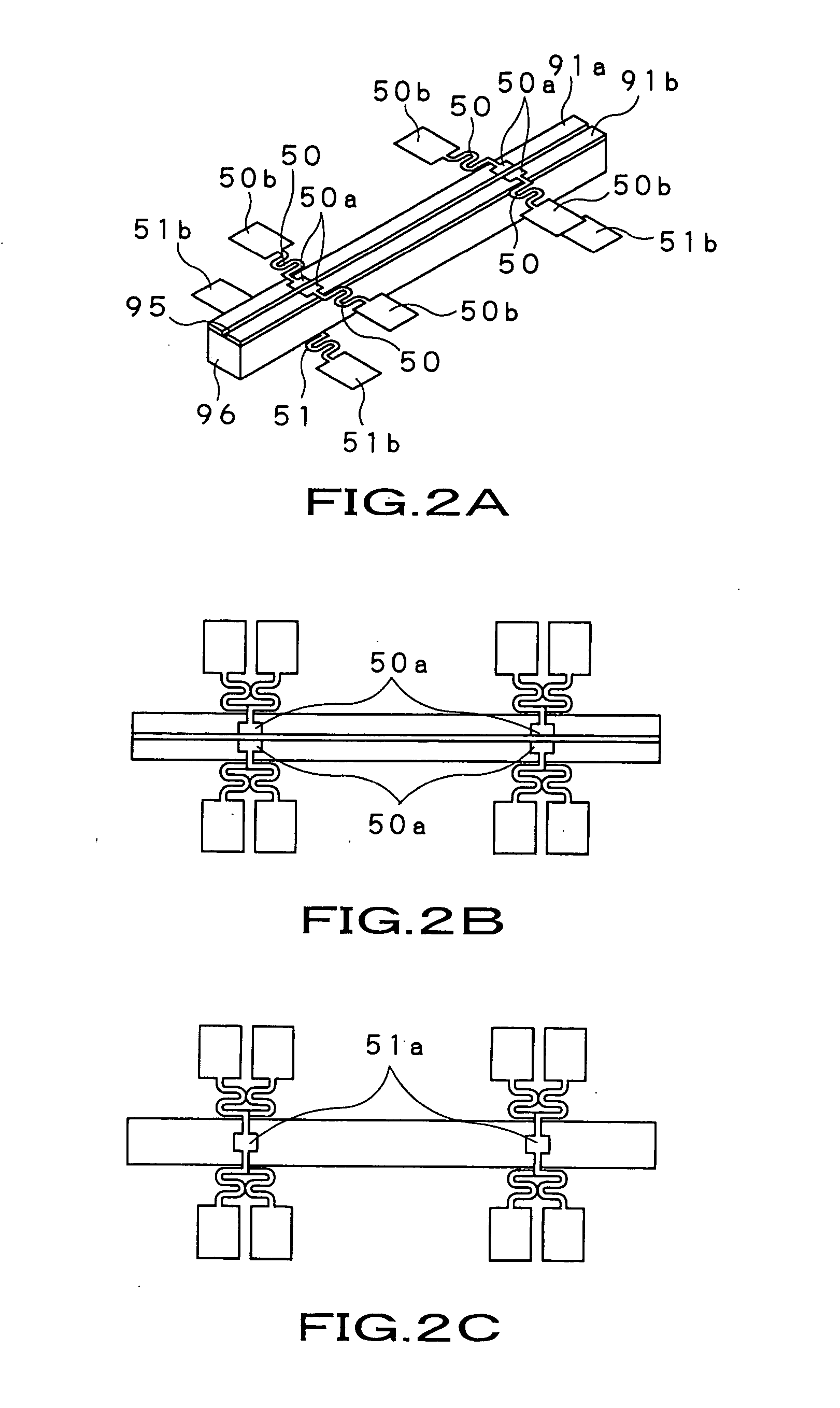
[0043]FIG. 3 is a perspective view of the vibrator provided in an angular velocity sensor 1 according to this invention. FIG. 4 is a block diagram illustrating a driving-detecting circuit 30 that is used in combination with the angular velocity sensor 1.

[0044] As FIGS. 3 and 4 show, the angular velocity sensor 1 according to the present embodiment has a vibrator 1a that functions as a vibration gyro.

[0045] As FIG. 3 shows, the vibrator 1a comprises a base 2 and piezoelectric layers 3 formed on the base 2. The vibrator 1a is a rectangular prism. It therefore has a rectangular or square cross section (hereinafter referred to as “cross section”), taken along a plane perpendicular to the lengthwise ...


PUM


Abstract

An angular velocity sensor having a pillar-shaped vibrator and support members. The support members clamp the vibrator from above and below, at those parts where vibration nodes are formed when the vibrator vibrates. The support members mechanically support the vibrator and are electrically connected to the vibrator. The support members have an uppermost layer covered with a silver or gold coating at the electrically connected parts. Each support member has arms and connecting parts provided at the distal ends of the arms. The connecting parts have a notch each. The support members are electrically and mechanically connected with conductive adhesive provided in the notches, applied to both surfaces of the connecting part and containing silver particles as conductive filler.

Description

BACKGROUND OF THE INVENTION [0001] 1. Field of the Invention [0002] The present invention relates to an angular velocity sensor that is designed to detect the shaking of a video camera, the motion of an object in a virtual-reality apparatus, or directions in a car-navigation system. [0003] This application claims priority of Japanese Patent Application No. 2004-024372, filed on Jan. 30, 2004, the entirety of which is incorporated by reference herein. [0004] 2. Description of the Related Art [0005] Angular velocity sensors widely used in public sector are so-called gyro-type angular velocity sensors. The vibration gyro-type angular velocity sensor has a rod-shaped vibrator and a piezoelectric element. The vibrator is vibrated at a predetermined resonant frequency. The piezoelectric element detects the Coriolis force generated due to the angular velocity. The sensor determines the angular velocity from the Coriolis force. [0006] The vibrator may be shaped like either a rectangular pri...

Claims


Application Information

Patent Timeline
IPC IPC(8): G01C19/56G01C19/5663G01P1/04G01P3/44
CPCG01C19/5663B60N3/083
Inventor MATSUNAGA, TORUKAWAMURA, TOSHIYUKISATOH, YOSHINORIMAEDA, TAKESHISASAKI, NAOYACHIBA, KAZUHIRO
Owner SONY CORP
Why Eureka
Try Eureka