Apparatus for transferring torque magnetically

a magnetic transfer and torque technology, applied in mechanical devices, electrostatic holding devices, asynchronous induction clutches/brakes, etc., can solve the problems of limited devices to specific set gaps and output, limited eddy current devices to three, and high cos

Active Publication Date: 2005-09-01
OSERAN WILLIAM A +1
View PDF49 Cites 41 Cited by
  • Summary
  • Abstract
  • Description
  • Claims
  • Application Information

AI Technical Summary

Benefits of technology

[0011] The present invention utilizes permanent magnets to transmit variable torque between two rotating elements. The torque between the elements is adjusted by mechanically varying the amount of magnetic flux passing between the elements by varying the extent to which the elements are axially overlapped. In a preferred embodiment of the apparatus, two concentric cylinders, one containing one or more rows of permanent magnets, is moved axially in order to progressively axially overlap a second cylindrical element containing electrically conductive and magnetically conductive elements. This progressive axial overlapping of the two cy

Problems solved by technology

An examination of the prior art shows that these eddy current devices are limited to three general types
These devices are limited to specific set gaps and output torque and are specific to low torque applications.
These devices are available in a wide range of horse power but are expensive, complicated and require a DC current and control to induce the torque.
There are applications where the DC current

Method used


Image

  • Apparatus for transferring torque magnetically
  • Apparatus for transferring torque magnetically
  • Apparatus for transferring torque magnetically

Examples


Embodiment Construction

[0022] Detailed descriptions of preferred embodiments are provided herein. It is to be understood, however, that the present invention may be embodied in various forms. Therefore, specific details disclosed herein are not to be interpreted as limiting, but rather as a basis for the claims and as a representative basis for teaching one skilled in the art to employ the present invention in virtually any appropriately detailed system, structure or manner.

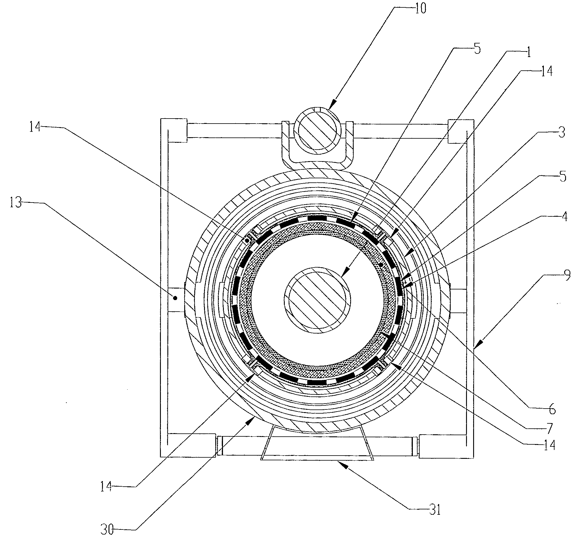
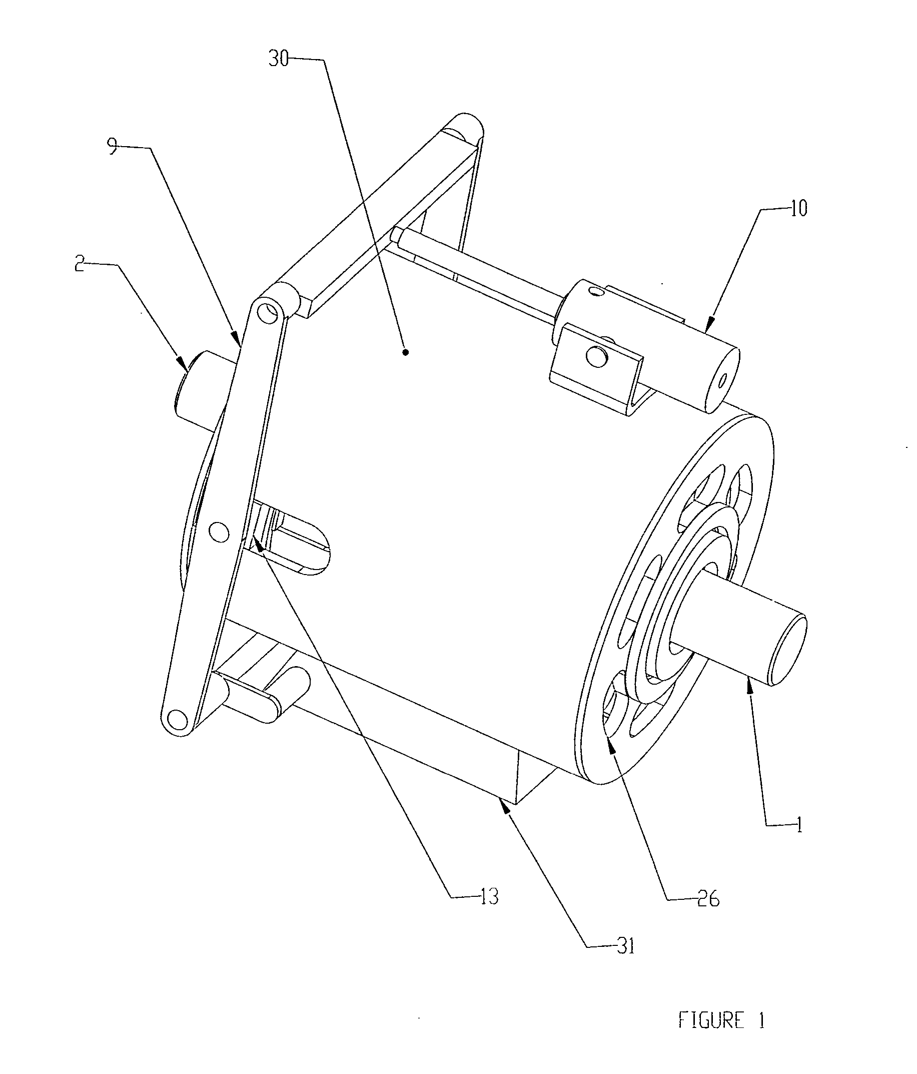
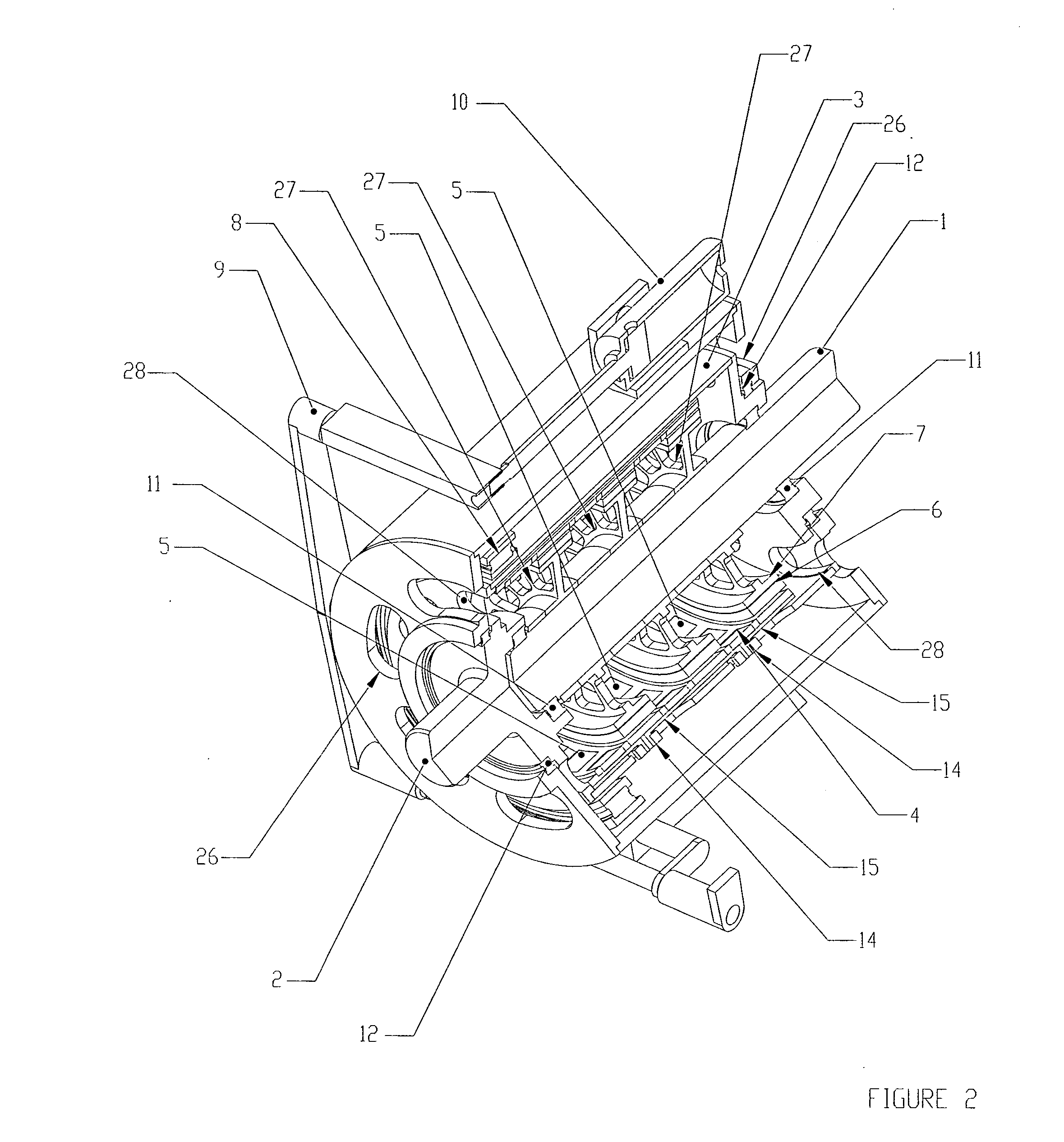
[0023] Referring to FIGS. 1 through 4, a first embodiment of the invention is shown and described as it applies to a variable speed drive application. The first part of the variable speed torque transfer apparatus described in this preferred embodiment consists of a primary rotary member comprising an input shaft rotor (2), a support cylinder (3), and a magnet-carrying rotor (4), all mechanically connected together, and constrained to rotate at the same angular velocity together. The second part of the variable speed torque transfer a...


PUM


Abstract

An apparatus for transferring torque magnetically with a primary rotary member and a secondary rotary member. The primary rotary member has permanent magnets mounted circumferentially on a cylinder, the secondary rotary member having a cylindrical geometry with electroconductive material arranged on its outer periphery and parallel to the axes of the rotary members. The secondary rotary member also having magnetically permeable material. The secondary rotary member is placed partially or totally inside the primary rotating member. The secondary rotary member's axial position relative to the primary rotating member can be varied by a suitable mechanical structure. This causes the two rotary members to axially overlap one another more or less as desired. Rotation of the primary rotary member causes rotation of the secondary rotary member, since magnetic flux lines emanating from the permanent magnets mounted on the primary rotating member, cut through all, or part of, the electroconductive material placed on the periphery of the secondary rotary member. This can vary the torque transmitted between the two rotary members, thereby enabling the varying of the rotational speed of the secondary rotary member relative to the primary rotary member.

Description

CROSS REFERENCE TO RELATED APPLICATIONS [0001] Not Applicable. STATEMENT REGARDING FEDERALLY SPONSORED RESEARCH OR DEVELOPMENT [0002] Not Applicable. DESCRIPTION OF ATTACHED APPENDIX [0003] Not Applicable. TECHNICAL FIELD OF THE INVENTION [0004] The present invention relates to rotational magnetic torque transfer devices utilizing two coaxial cylinders overlapping one another wherein one cylinder contains a row(s) of permanent magnets and the other cylinder contains a ring(s) of electroconductive material. BACKROUND OF THE INVENTION [0005] It is desirable to devise a permanent magnet excited mechanism for transmitting variable torque in drive applications. Specifically there is a need to couple constant speed devices such as motors or engines to variable output speed and torque devices such as pump impellers, fans, propellers, wheels, etc. Transmission devices including various eddy current clutches have been in use for some time in various forms. An examination of the prior art sho...

Claims


Application Information

Patent Timeline
IPC IPC(8): H02K49/10H02K51/00
CPCH02K49/02Y10T464/30H02K51/00H02K49/106
Inventor CORBIN, PHILIP IIIDAHLIN, ROBERT L.MOLNAR, JOHN A.RUSCONI, JOHN B.STRONG, WALTER F.
Owner OSERAN WILLIAM A
Why Eureka
Try Eureka