Spark plug

a technology of spark plugs and spark plugs, which is applied in the field of spark plugs, can solve the problems of no improvement of the center electrode, low efficiency and even malfunction, and the prior art suffered from two, so as to increase the output torque of the cylinder, reduce the pollutant contained in the exhaust gas, and increase the sparking efficiency

Inactive Publication Date: 2005-09-01
CHANG CHIN FA +1
View PDF3 Cites 5 Cited by
  • Summary
  • Abstract
  • Description
  • Claims
  • Application Information

AI Technical Summary

Benefits of technology

[0008] It is an object of the present invention to provide a spark plug having an improved electric bar so as to increase sparking efficiency, increase output torque of the cylinder, decrease pollutant contained in exhaust gas, and increase driving safety.

Problems solved by technology

However, the prior art suffered from two disadvantages.
Further, a lot of carbon may accumulate on the ground electrode 92 after a short period time of operation, resulting in a low efficiency and even malfunction.
However, there is no improvement on the center electrode 93.
Thus, the total performance is still low.
Another drawback of the patent is that excessive heat may be generated between the center electrode 93 and the electrodes 95 when sparking frequency of the spark plug increases from 5,000 RPM (revolutions per minute) to the range of 10,000 RPM to 12,000 RPM for increasing output torque of the engine.
This may cause the end of the insulator shell 94 (i.e., ceramic cylindrical member) to break after a short period of time of operation due to poor heat dissipation.
The broken ceramic cylindrical member may undesirably scrape the inner wall of the cylinder.
For other automobiles having such spark plug may not have a smooth sparking operation due to the low temperature of the center electrode 93 and the electric current only having a normal voltage.
As an end, the applications of the spark plug are limited.
However, there is no disclosure of how to improve the electric beam 96 for increasing the sparking efficiency.

Method used


Image

  • Spark plug
  • Spark plug
  • Spark plug

Examples


Embodiment Construction

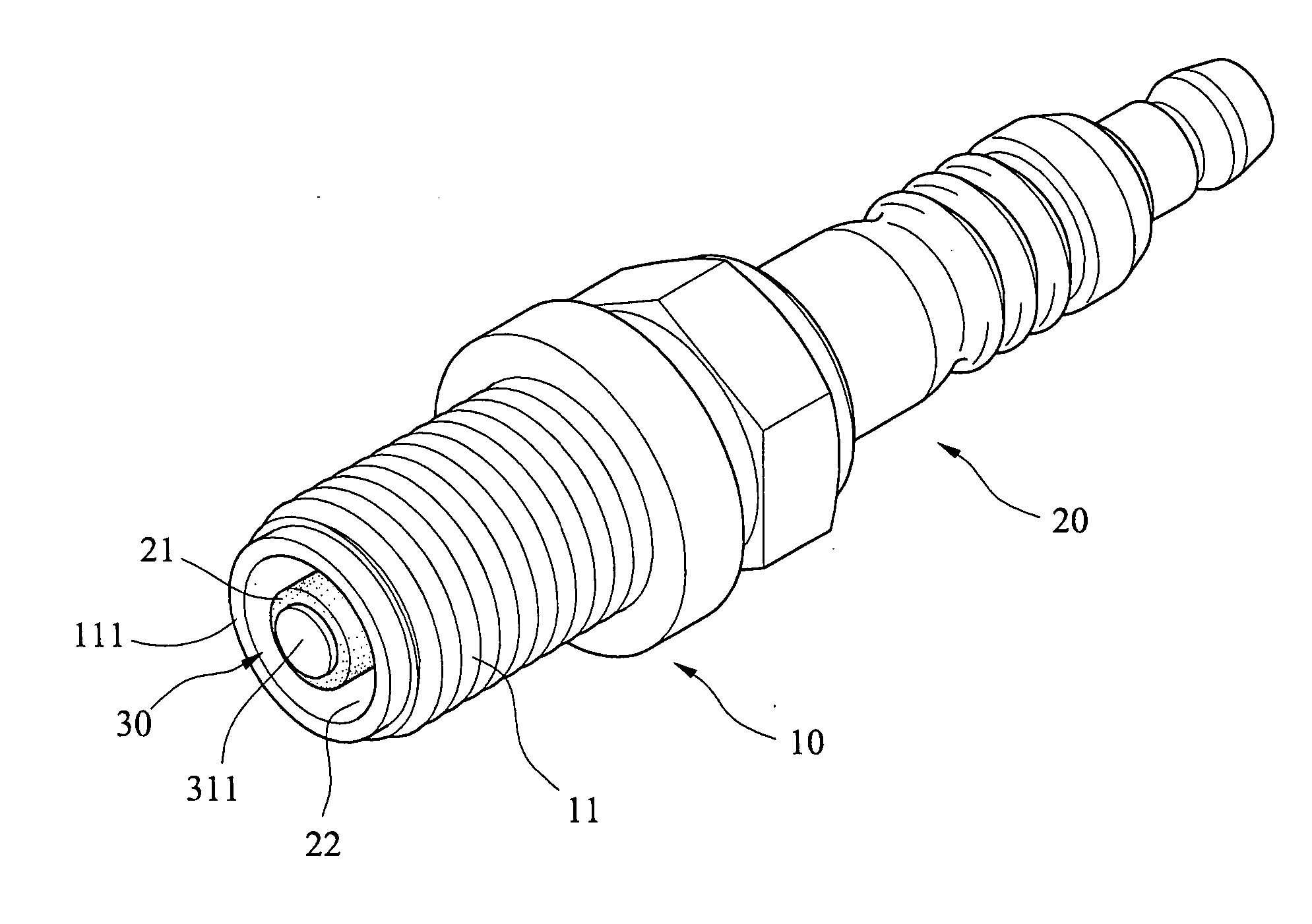
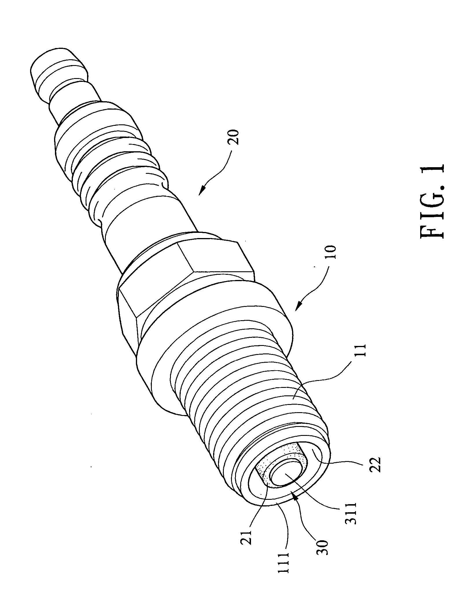
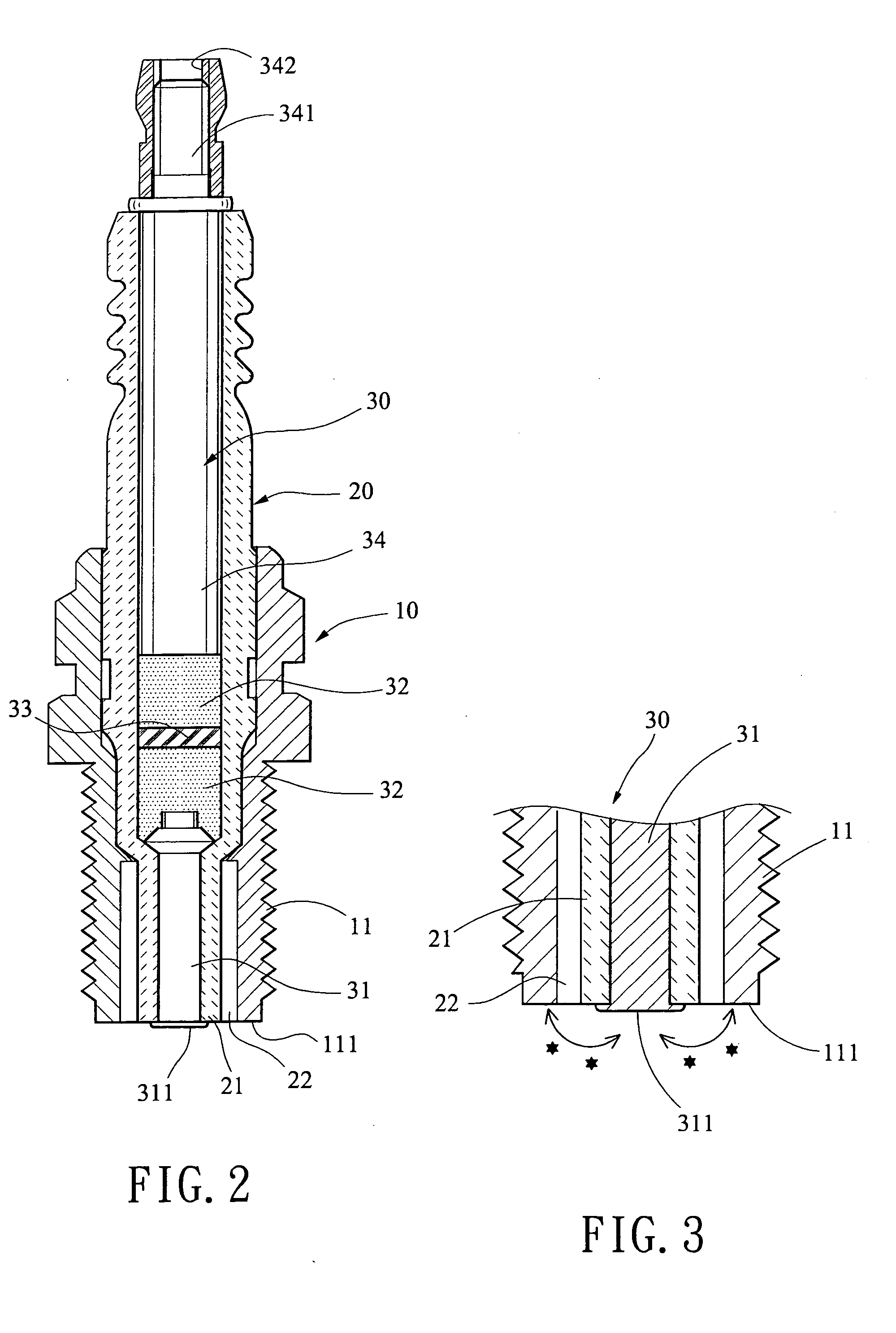
[0023] Referring to FIGS. 1 to 3, there is shown a spark plug constructed in accordance with a first preferred embodiment of the invention. The spark plug comprises a center electrode 30, an insulation shell 20 formed of ceramic material, the insulation shell 20 being sleeved on the center electrode 30, and a metal shell 10 sleeved on a portion of the insulation shell 20. The metal shell 10 comprises an externally threaded extension 11 at one end, the externally threaded extension 11 being matingly coupled to a threaded aperture (not shown) on an internal wall of the cylinder so as to mount the spark plug therein. The insulation shell 20 comprises a ceramic cylindrical member 21 at an open end thereof. A cylindrical gap 22 is formed between the ceramic cylindrical member 21 and the externally threaded extension 11. The center electrode 30 comprises a first electrode 31 at one end, a second electrode 34 at the other end, and an intermediate electric bar (i.e., potential intensifying ...


PUM

PropertyMeasurementUnit
temperatureaaaaaaaaaa
electric currentaaaaaaaaaa
diameteraaaaaaaaaa

Abstract

A spark plug comprises a center electrode, an electric bar in the center electrode, the electric bar being composed of about 50 wt % to about 75 wt % of binder, about 25 wt % to about 24 wt % of carbon powder, and about 25 wt % to about 1 wt % of magnesium oxide, and including a resistor, a ceramic insulation shell sleeved on the center electrode and including a ceramic cylindrical member at an open end spaced apart from the center electrode by a gap, and a metal shell sleeved on the insulation shell. The center electrode comprises a flat enlarged end for partially covering and supporting the ceramic cylindrical member. The spark plug has the advantages of increased efficiency, increased output torque by increasing electric potential by the electric bar, and decreased pollutant contained in exhaust gas. Also, the cylinder is prevented from being damaged by the broken ceramic cylindrical member.

Description

BACKGROUND OF THE INVENTION [0001] 1. Field of the Invention [0002] The present invention relates to spark plugs of internal-combustion engine and more particularly to such a spark plug with improved characteristics. [0003] 2. Description of Related Art [0004] Spark plug is an important component of an internal-combustion engine. It is fitted into the cylinder to ignite the air / fuel mixture therewithin. A conventional spark plug 90 is shown in FIG. 7 and comprises a center electrode 91 having the other end electrically coupled to a high voltage source, and a bent ground electrode 92 having an open end proximate one end of the center electrode 91 so as to form a gap therebetween. In operation, an electric current supplied from the high voltage source is carried into the cylinder for sparking between the center electrode 91 and the ground electrode 92 (i.e., at the gap) in the presence of the air / fuel mixture. However, the prior art suffered from two disadvantages. For example, the pr...

Claims


Application Information

Patent Timeline
Patent Type & Authority Applications(United States)
IPC IPC(8): H01T13/34
CPCH01T13/34
Inventor CHANG, CHIN-FAPAN, JUN-WEI
Owner CHANG CHIN FA
Why Eureka
Try Eureka