Voltage-controlled oscillator, radio communication apparatus and voltage-controlled oscillation method

a technology of radio communication apparatus and voltage control, which is applied in the direction of oscillator, pulse automatic control, pulse technique, etc., can solve the problems of phase noise characteristic degradation, and achieve the effect of curbing the influence of variation or noise and curbing the degradation of phase noise characteristi

Active Publication Date: 2005-09-01
PANASONIC CORP
View PDF7 Cites 39 Cited by
  • Summary
  • Abstract
  • Description
  • Claims
  • Application Information

AI Technical Summary

Benefits of technology

[0054] According to the present invention, it is possible to provide the voltage-controlled oscillator capable of curbing influence of the variation or the noise in the power supply voltage, the radio communication apparatus and the voltage-controlled oscillation method using the voltage-controlled oscillator, or to provide the voltage-controlled oscillator, radio communication apparatus and voltage-controlled oscillation method capable of curbing the degradation of the phase noise characteristic.

Problems solved by technology

A configuration of level-shifting a control voltage has a problem that a phase noise characteristic is degraded due to the noise generated from a transistor such as FET.

Method used


Image

  • Voltage-controlled oscillator, radio communication apparatus and voltage-controlled oscillation method
  • Voltage-controlled oscillator, radio communication apparatus and voltage-controlled oscillation method
  • Voltage-controlled oscillator, radio communication apparatus and voltage-controlled oscillation method

Examples


first embodiment

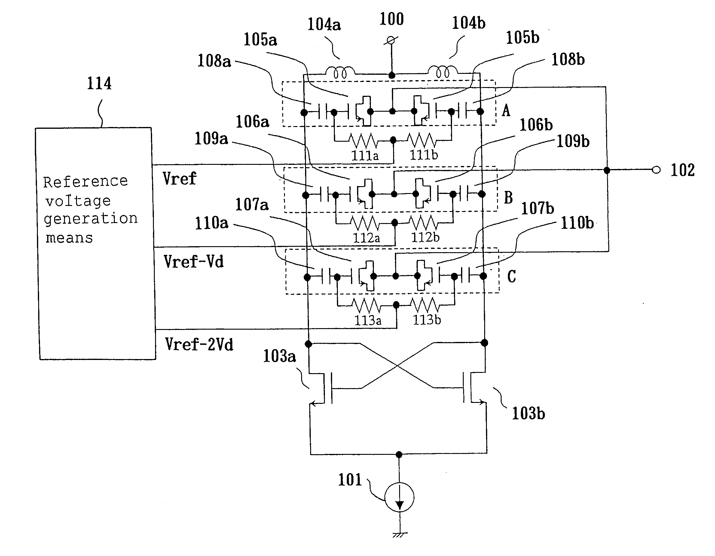
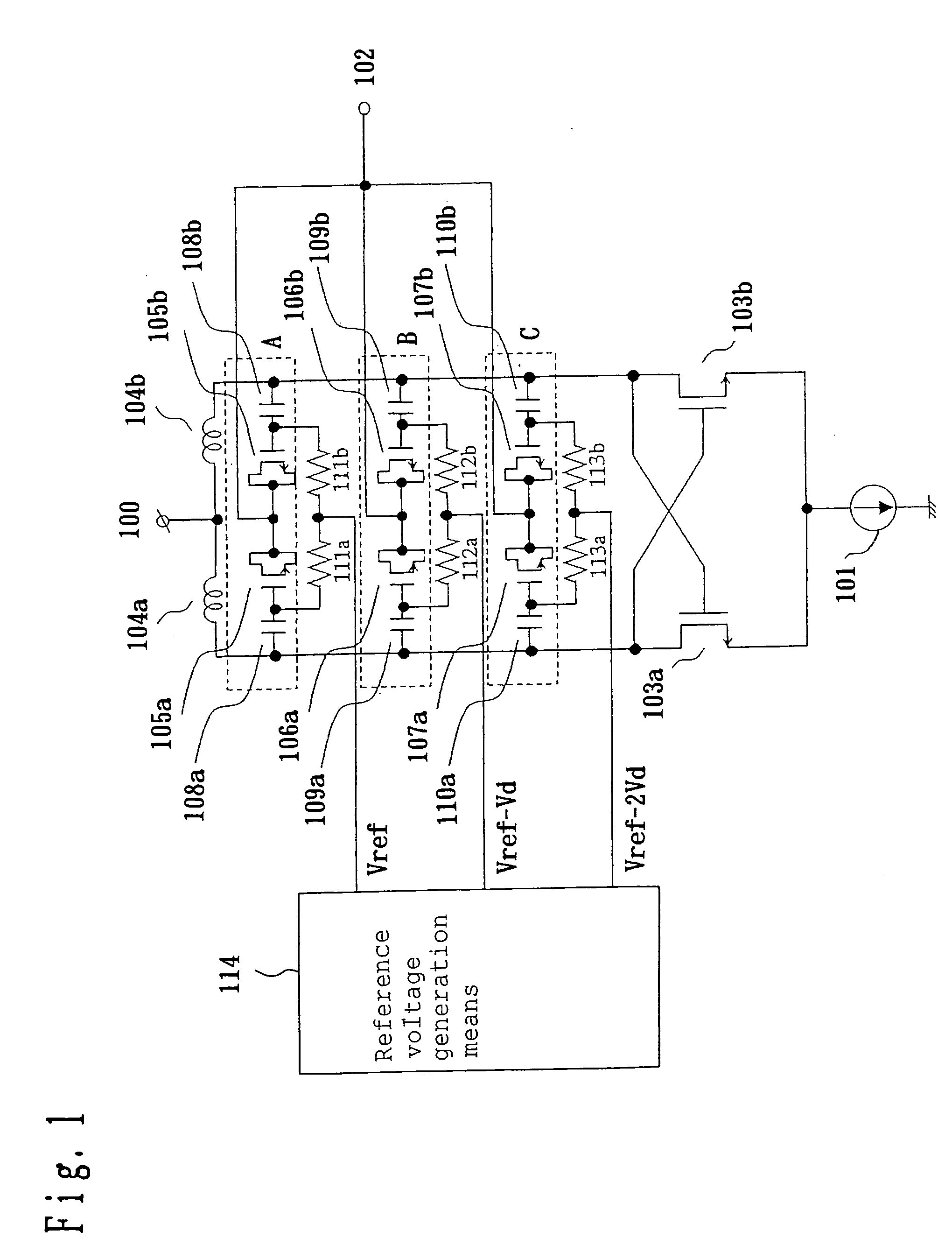
[0090]FIG. 1 shows a configuration of a voltage-controlled oscillator according to a first embodiment of the present invention, in which a bias circuit and so on is omitted.

[0091] In FIG. 1, reference numeral 100 denotes a power source terminal as an example of a power supply terminal of the present invention, 101 denotes a current source, and 102 denotes a frequency control terminal. Reference numerals 103a and 103b denote oscillation transistors, 104a and 104b denote inductors, 105a, 105b, 106a, 106b, 107a and 107b denote variable capacitance elements utilizing a gate capacitance used in a CMOS process, and 108a, 108b, 109a, 109b, 110a and 110b denote DC-cut capacitors as an example of a blocking capacitor of the present invention. Reference numerals 111a, 111b, 112a, 112b, 113a and 113b denote high-frequency blocking resistances, and 114 denotes reference voltage generation means.

[0092] The inductors 104a and 104b are series-connected, where the power source terminal 100 is con...

second embodiment

[0119]FIG. 8 shows a configuration of the voltage-controlled oscillator according to a second embodiment of the present invention, in which the same portions as those previously described are given the same symbols and a description thereof will be omitted.

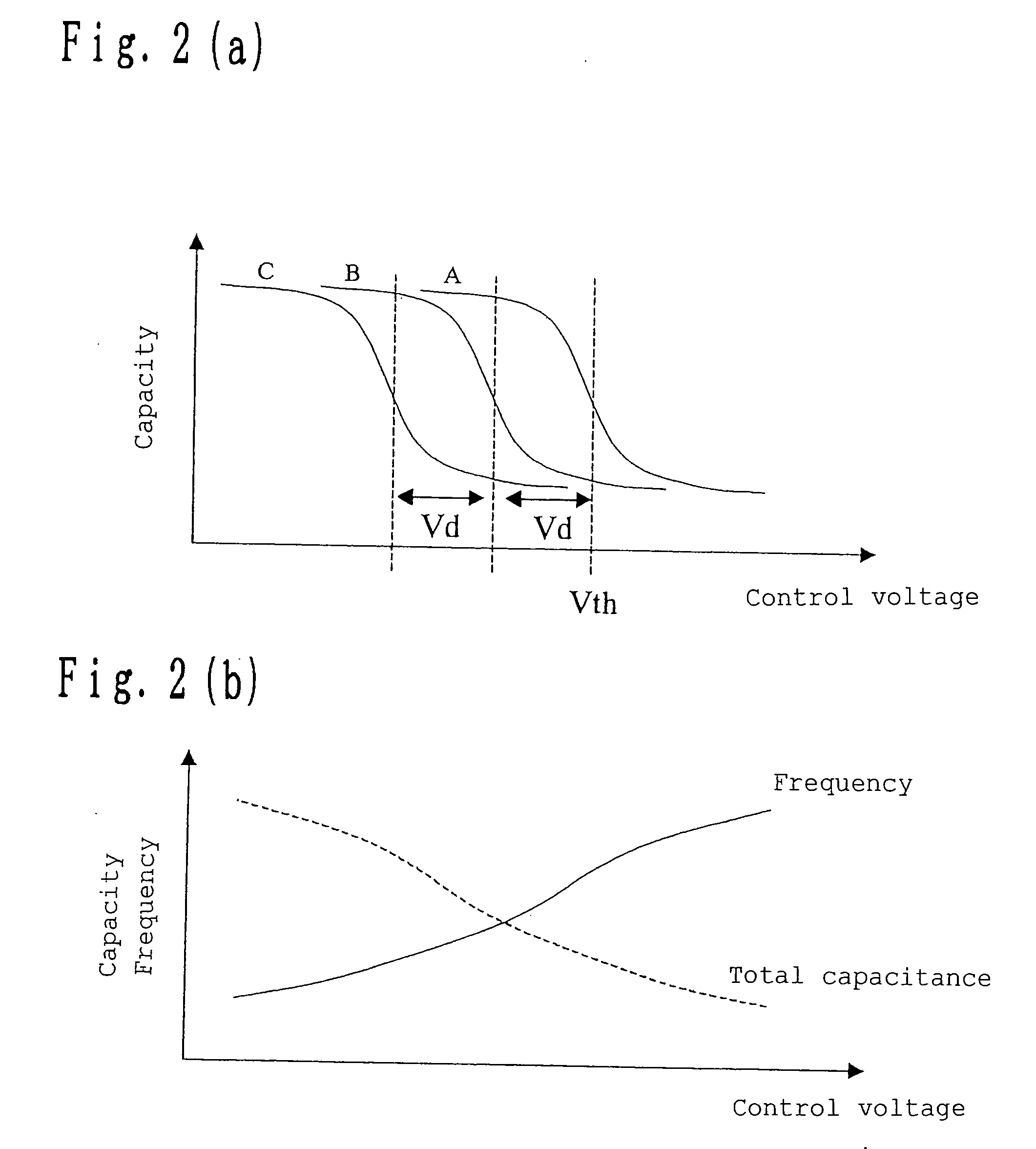
[0120] As for the voltage-controlled oscillator according to the first embodiment, there are the cases where there is a frequency domain in which the change in the capacitance of the variable capacitance element gets saturated even if the control voltage is changed. The voltage-controlled oscillator according to this embodiment relates to the voltage-controlled oscillator capable of changing the capacitance of the variable capacitance circuit according to a frequency band.

[0121] In FIG. 8, reference numerals 141a and 141b denote frequency band setting variable capacitance elements, 144a, 144b and 144c denote the variable capacitance circuits, and 140 denotes a frequency band setting terminal. The variable capacitance elements 14...

third embodiment

[0145] The voltage-controlled oscillator according to a third embodiment of the present invention will be described next by referring to FIGS. 17 to 20.

[0146]FIG. 17 shows a configuration example of the voltage-controlled oscillator according to this embodiment. The components in common with the first and second embodiments are given the same reference numerals, and a description thereof will be omitted. The voltage-controlled oscillator shown in FIG. 17 has variable capacitance elements 305a and 305b series-connected to constitute the variable capacitance circuit A, and has variable capacitance elements 306a and 306b series-connected to constitute the variable capacitance circuit B. The gate sides of the variable capacitance elements 305a, 305b, 306a and 306b are connected to the power supply voltage side without involving the DC-cut capacitors 110a and 110b. The reference voltage generation means 114 is not used in this embodiment.

[0147] In the circuit shown in FIG. 17, the vari...


PUM


Abstract

A voltage-controlled oscillator having an inductor circuit, n pieces (n is two or more) of variable capacitance circuit having variable capacitance elements, negative resistance circuits, and reference voltage generation means of generating a reference voltage from a power supply voltage, and wherein a predetermined reference voltage is inputted to some terminals of the variable capacitance elements of the n pieces of variable capacitance circuit, a control voltage is inputted to the other terminals thereof, and of the variable capacitance elements of the n pieces of variable capacitance circuits, the predetermined reference voltage inputted to some terminals of the variable capacitance elements of at least two pieces of the variable capacitance circuit is different.

Description

BACKGROUND OF THE INVENTION [0001] 1. Field of the Invention [0002] The present invention relates to a voltage-controlled oscillator used for a radio communication device, a radio communication apparatus using the voltage-controlled oscillator and a voltage-controlled oscillation method. [0003] 2. Related Art of the Invention [0004] A voltage-controlled oscillator is widely used as a means of generating a local oscillation signal of a radio communication device. [0005]FIG. 12 shows a configuration example of such a voltage-controlled oscillator in the past. [0006] In FIG. 12, reference numerals 1a and 1b denote oscillation transistors, 2a and 2b denote inductors, and 3a and 3b denote variable capacitance elements. Reference numeral 4 denotes a power supply terminal, 5 denotes a frequency control terminal, and 6 denotes a current source. A bias circuit and so on are omitted in FIG. 12. [0007] Hereafter, operation of the voltage-controlled oscillator in the past will be described by r...

Claims


Application Information

Patent Timeline
Patent Type & Authority Applications(United States)
IPC IPC(8): H03B1/00H03B5/00H03B5/12H03B7/06H03C3/22H04B1/16
CPCH03B2201/025H03L7/099H03B5/1228H03B5/1293H03B5/1265H03B5/1253H03B5/1215
Inventor TAKINAMI, KOJIADACHI, HISASHIENDOH, TOKIO
Owner PANASONIC CORP
Why Eureka
Try Eureka