Electrical connector

a technology of electrical connectors and connectors, applied in the direction of printed circuits, electrical devices, etc., can solve the problems of poor heat resistance and flow molding properties, compromising the stability of the connection, etc., and achieve the effects of better flow molding properties, better pin elasticity, and better heat resistan

Inactive Publication Date: 2005-09-01
NELTRON INDAL
View PDF4 Cites 30 Cited by
  • Summary
  • Abstract
  • Description
  • Claims
  • Application Information

AI Technical Summary

Benefits of technology

[0004] It is therefore a primary object of the invention to provide an electrical connector for electrical board to board connection with better heat resistance, better flow molding properties, and better pin elasticity.
[0005] In order to achieve the objective set forth, an electrical connector in accordance with the present invention comprises a rectangular insulated body and a plurality of electrical pins; the insulated body is made of a liquid crystal polymer (LCP) with good heat resistance and flow molding properties; the electrical pins are made of phosphor bronze with better elasticity; the insulated body has a bottom wall for contacting a printed circuit board (PCB); a plurality of pin containers pass through the bottom wall to contain the electrical pins; a plurality of protruding pillars are provided under the bottom wall, corresponding in position to the holes on the circuit board such that the insulated body can be positioned accurately on the circuit board with the protruding pillars. Furthermore, a soldering section on each electrical pin is to be soldered onto the PCB using SMT (Surface Mount Technology).

Problems solved by technology

The electrical connector described above is often made of materials that have poor heat resistance and flow molding properties.
Moreover, the connection pin 9 might not have good elasticity, thus compromising the stability of the connection.

Method used


Image

  • Electrical connector
  • Electrical connector
  • Electrical connector

Examples


Embodiment Construction

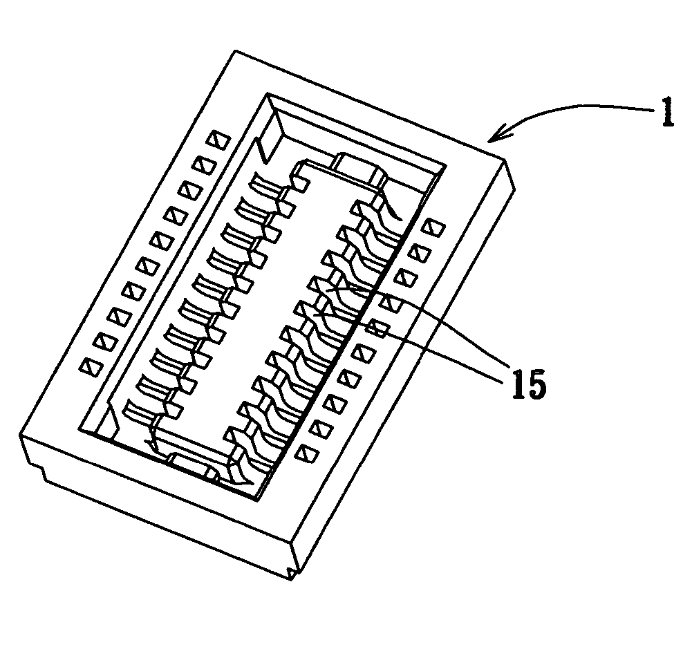
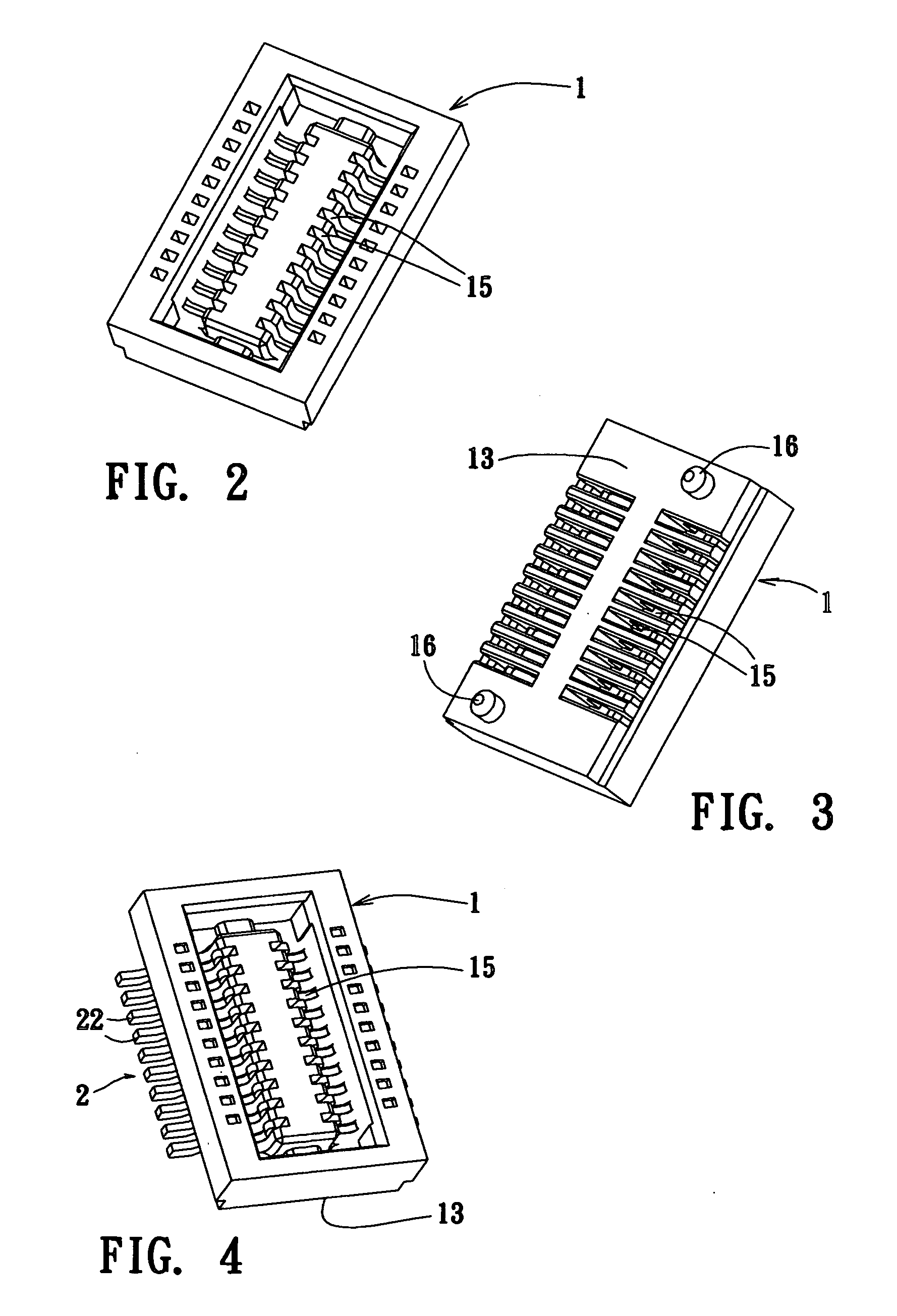
[0014] Referring to FIG. 2 to FIG. 4, the female connector as a preferred embodiment of the present invention comprises a rectangular insulated body 1 and a plurality of electrical pins 2; the insulated body 1 comprises a bottom wall 13 for contacting a PCB (not shown), a plurality of pin containers 15 passing through the bottom wall 13 for containing the electrical pins 2, and a plurality of protruding pillars 16 under the bottom wall 13, corresponding in position to the holes on the PCB such that the insulated body 1 can be positioned accurately on the PCB with the protruding pillars 16. A soldering section 22 on each electrical pin 2 is to be soldered onto the PCB using SMT (Surface Mount Technology).

[0015] Referring to FIG. 5 to FIG. 7, the male connector as another embodiment of the present invention comprises a rectangular insulated body 1 and a plurality of electrical pins 2; the electrical pins 2 are inside the corresponding pin containers 15; a plurality of protruding pill...


PUM


Abstract

An electrical connector comprising a rectangular insulated body and a plurality of electrical pins has been described and claimed. The insulated body is made of a liquid crystal polymer (LCP) with good heat resistance and flow molding properties; the electrical pins are made of phosphor bronze with better elasticity. The insulated body has a bottom wall for contacting PCB, a plurality of pin containers passing through the bottom wall for containing the electrical pins, and a plurality of protruding pillars under the bottom wall, corresponding in position to holes on the PCB such that the insulated body can be positioned accurately on the PCB with the protruding pillars. A soldering section is on each electrical pin to be soldered onto the PCB using SMT (Surface Mount Technology).

Description

BACKGROUND OF THE INVENTION [0001] I. Field of the Invention This invention relates generally to an electrical connector and, more specifically, to an electrical connector that connects two circuit boards. [0002] II. Description of the Related Art Heretofore, it is known that the board to board female connector, as shown in FIG. 1, consists of an insulated body 8 made of injection plastic material in rectangular shape having a first side wall 81 and a second side wall 82 on the longer direction sides, and a bottom wall 83 linking the bottom of the first side wall 81 and the bottom of the second side wall 82; the first side wall 81, the second side wall 82 and the bottom wall 83 together form a concave connection section 84 for receiving a board to board male connector (not shown). A plurality of pin containers 85 pass through the bottom wall 83 of the insulated body 8, link to the connection section 84 and stretch to the first side wall 81 and the second side wall 82; each pin conta...

Claims


Application Information

Patent Timeline
Patent Type & Authority Applications(United States)
IPC IPC(8): H01R12/00
CPCH01R12/716
Inventor HUANG, PETER
Owner NELTRON INDAL
Why Eureka
Try Eureka