Attic ventilation system

a ventilation system and attic technology, applied in ventilation systems, lighting and heating apparatus, heating types, etc., can solve the problems of inconvenient living conditions, inconvenient installation, and ineffective insulation in preventing the flow of heated air from the attic, so as to reduce the complexity of attic installation, time and cost, and the effect of less expensiv

Inactive Publication Date: 2005-09-01
DEMETRY MR PAUL M
View PDF8 Cites 53 Cited by
  • Summary
  • Abstract
  • Description
  • Claims
  • Application Information

AI Technical Summary

Benefits of technology

[0012] In accordance with the present invention, a ventilation system is provided including a novel design utilizing inexpensive materials along with existing passive roof vents to exhaust the heated attic air. A roof vent opening is typically located at or near the highest part of the attic to allow the hottest attic air to escape. The ventilation system of the present invention is placed inside the attic, directly underneath the roof vent opening. The ventilation system includes a fan housing and an air sealer in fluid communication with the vent. The air sealer creates a seal between the fan housing and the inside of the roof. The air sealer also acts as an air diverter, directing the air toward the vent. The air sealer may be constructed of flexible material such as a woven fabric (e.g., canvas). The fan, supported by the air sealer, may comprise inexpensive propeller fans positioned under the roof opening. The fan is configured to generate airflow that forces the hot attic air into the air sealer and out of the attic (via the roof vent opening). Adjust...

Problems solved by technology

Insulation, however, is only partially effective in preventing the flow of heated air from the attic to the cooler, occupied space below.
These higher temperatures cause uncomfortable living conditions, as well as add wear and tear on air conditioning units, which must run continuously to keep occupied spaces cool.
In addition, roofing material such as shingles literally bake from the inside, causing the shingles to crack and age prematurely.
Unfortunately, convection requires the attic air to be very hot before convection naturally occurs.
The air movement using this system is, however, ineffective.
The removal of the heated attic air utilizing attic fans reduces attic temperatures, thus resulting in lower temperatures in adjacent spac...

Method used


Image

  • Attic ventilation system
  • Attic ventilation system
  • Attic ventilation system

Examples


Embodiment Construction

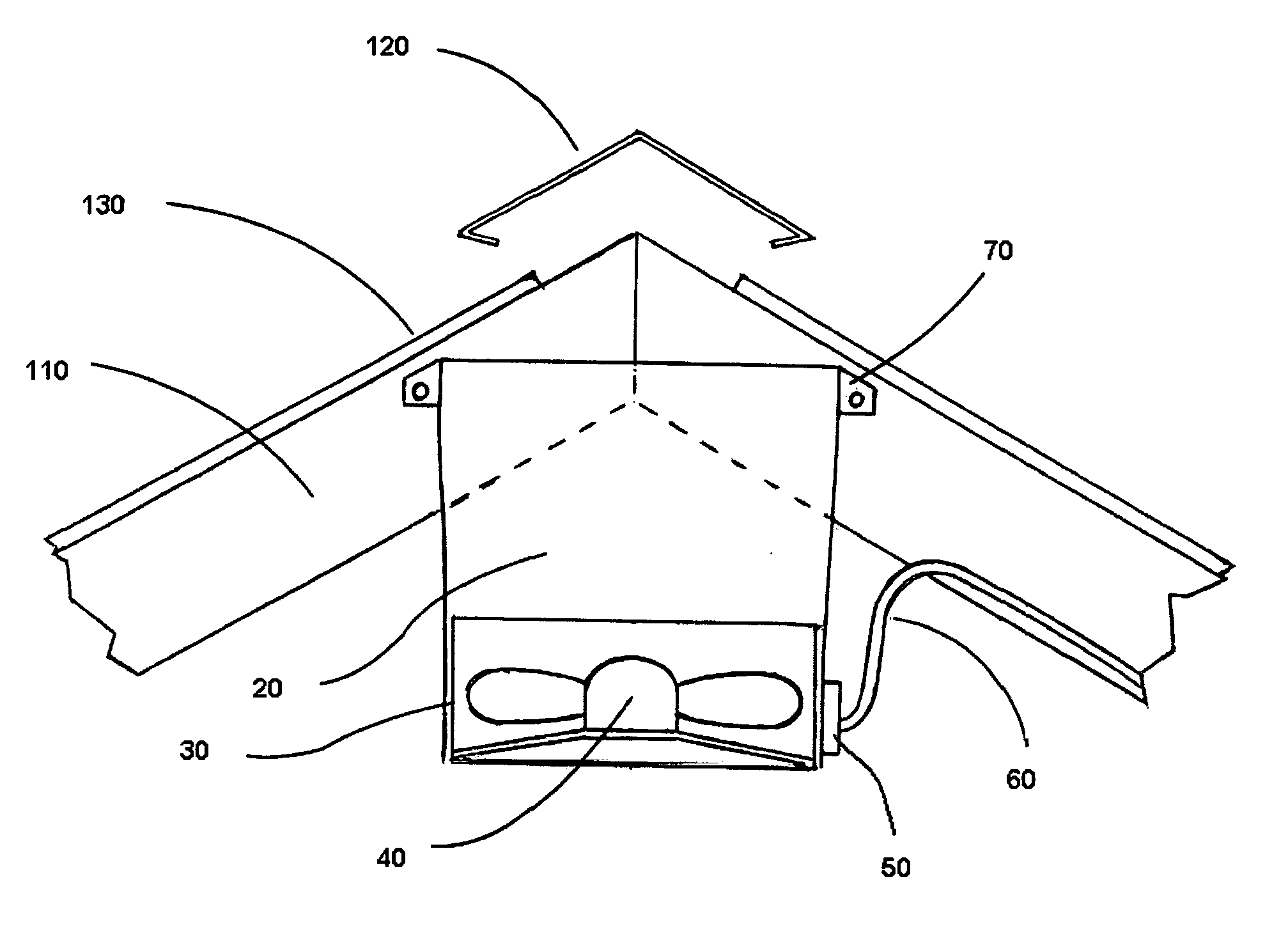
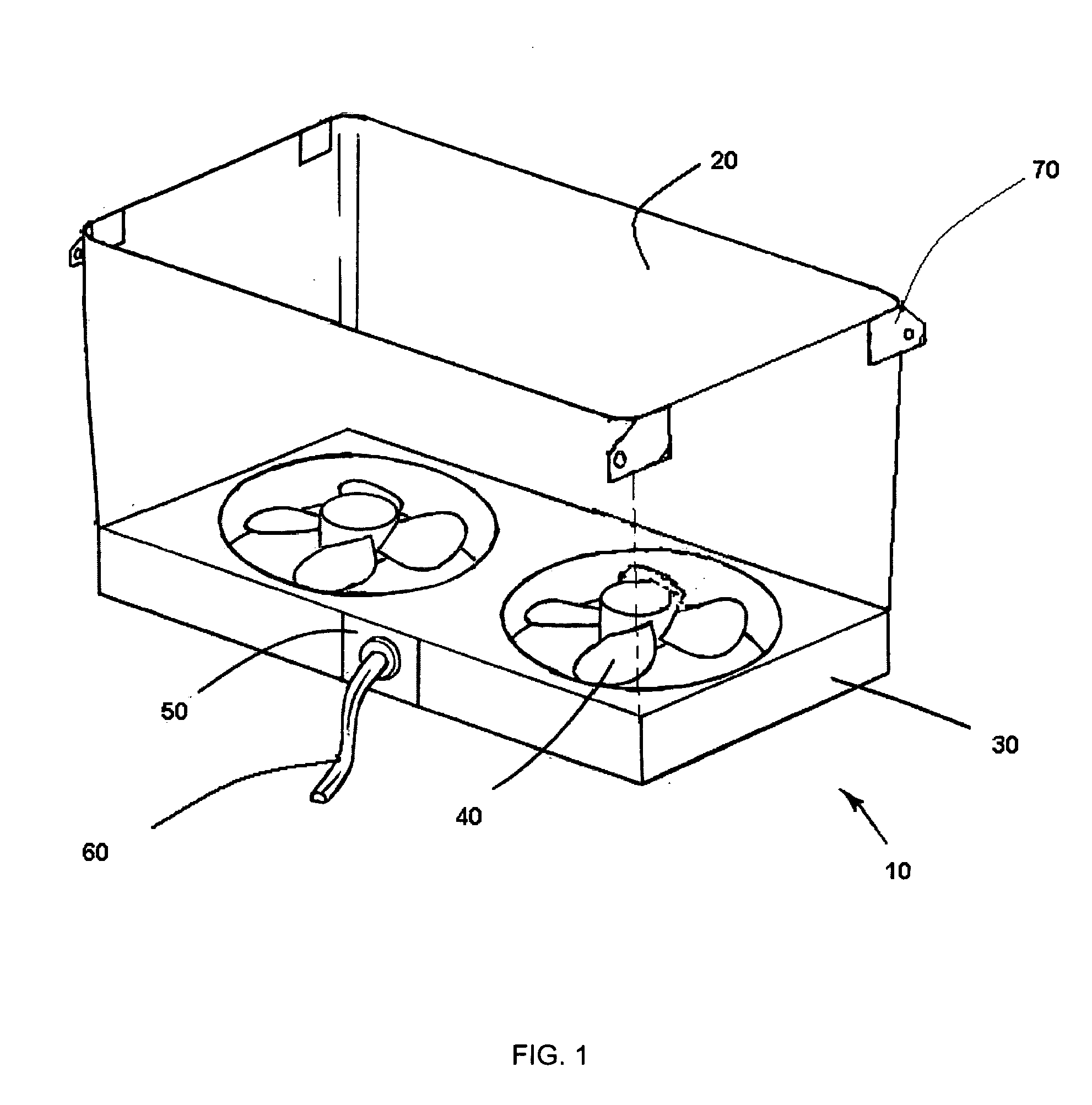
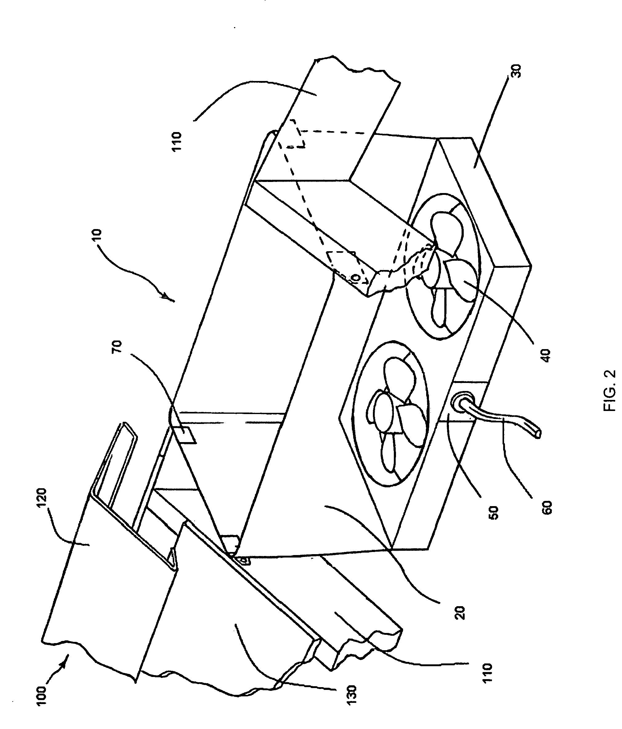
[0019]FIGS. 1-3 illustrate a ventilation system according to an embodiment of the invention. As shown, the system 10 may include an air sealer 20 coupled to a fan housing 30 (also called a flow generator). The air sealer 20 includes a structure operable to direct air toward a vent located in the roof of a building. Specifically, as shown in FIG. 1, the air sealer 20 may comprise a duct having open top and bottom ends. The air sealer 20 may be connected to the fan housing 30 such that a substantially fluid (air) tight seal is formed. Preferably, the air sealer 20 comprises flexible material to enable the sealer 20 to fit between variably spaced rafters (e.g., the flexible material may be contorted to fit a given space). By way of specific example, the material comprising the air sealer 20 may include flexible non-woven and woven material (e.g., canvas) attached to the perimeter of the fan housing 30.

[0020] The fan housing 30 may include one or more exhaust fans 40 configured to draw...


PUM


Abstract

An apparatus to ventilate attic space of a structure such as a home or building is provided. The apparatus includes a flexible air sealer and a fan housing unit. The apparatus is connected to trusses or rafters of the structure. The apparatus is placed directly below a roof vent, with the air sealer creating a seal between the fan housing and the roof vent. The air sealer supports propeller fans located in the fan housing. The airflow caused by the fan directs air into the flexible air sealer, through the openings of the roof vent, and out of the attic space. The apparatus may further include adjustable truss connectors that are removably attached to the air sealer and the trusses to allow the apparatus to be installed between variably spaced rafters.

Description

CROSS REFERENCE TO RELATED APPLICATIONS [0001] This application claims priority from U.S. Provisional Patent Application Ser. No. 60 / 546,709 entitled “Roof Vent Attic Ventilation Fan” and filed Feb. 23, 2004. The disclosure of the above-mentioned provisional application is incorporated herein by reference in its entirety.FIELD OF THE INVENTION [0002] The present invention relates to a ventilation system and, in particular, to an attic ventilation fan operable to remove heated air from the attic space of a building. BACKGROUND [0003] The purpose of attic ventilation fans is to remove heated air from the attic space of a building. The attic space typically includes the space below the roof a building, but above the ceiling of an occupied space below. This space, by virtue of its location in the building, traps heated air. For example, in the summer, the sun shining on the roof of a structure causes temperatures inside an attic to reach temperatures as high as 150° Fahrenheit. As a res...

Claims


Application Information

Patent Timeline
IPC IPC(8): F24F7/02
CPCF24F7/025
Inventor DEMETRY, PAUL MICHAELFRANCOVITCH, THOMAS F. SR.
Owner DEMETRY MR PAUL M
Why Eureka
Try Eureka