
Collaboration server, collaboration system, and method and program for collaboration server and system

a collaboration server and collaboration technology, applied in the field of collaboration systems, can solve the problems of increasing the traffic load on the network, the problem of large amount of data communicated as image data to be transmitted and received, and the problem of conventional collaboration techniques, etc., to achieve the effect of reducing the traffic of communication and high general versatility

Inactive Publication Date: 2005-09-01
IBM CORP
View PDF3 Cites 76 Cited by
  • Summary
  • Abstract
  • Description
  • Claims
  • Application Information

AI Technical Summary

Benefits of technology

[0022] An object of the present invention is to reduce traffic communication between computers in collaborative work in a collaboration system with computers interconnected through a network.
[0023] Another object of the present invention is to provide a collaboration system having high general versatility and a method for the collaboration system in which displays and various operations are synchronized without any platform and OS dependences and without the need for any special application program.
[0031] Also, each time the work screen controller accepts from one of the terminal apparatuses a request made by designating a predetermined point on the Web page, it adds an anchor tag (a record anchor described below) to the data file for the Web page in correspondence with the point designated by the request, thereby facilitating return to the point set as an attention point in a collaborative work. Further, the chat function performing unit holds a log of texts exchanged in the chat, and the work screen controller accepts from one of the terminal apparatuses a request made by designating a predetermined point on the Web page, and thereafter associates the log of the chat between the acceptance of the request and the acceptance of another request subsequently made by designating another point on the Web page with the anchor tag corresponding to the predetermined point on the Web page.
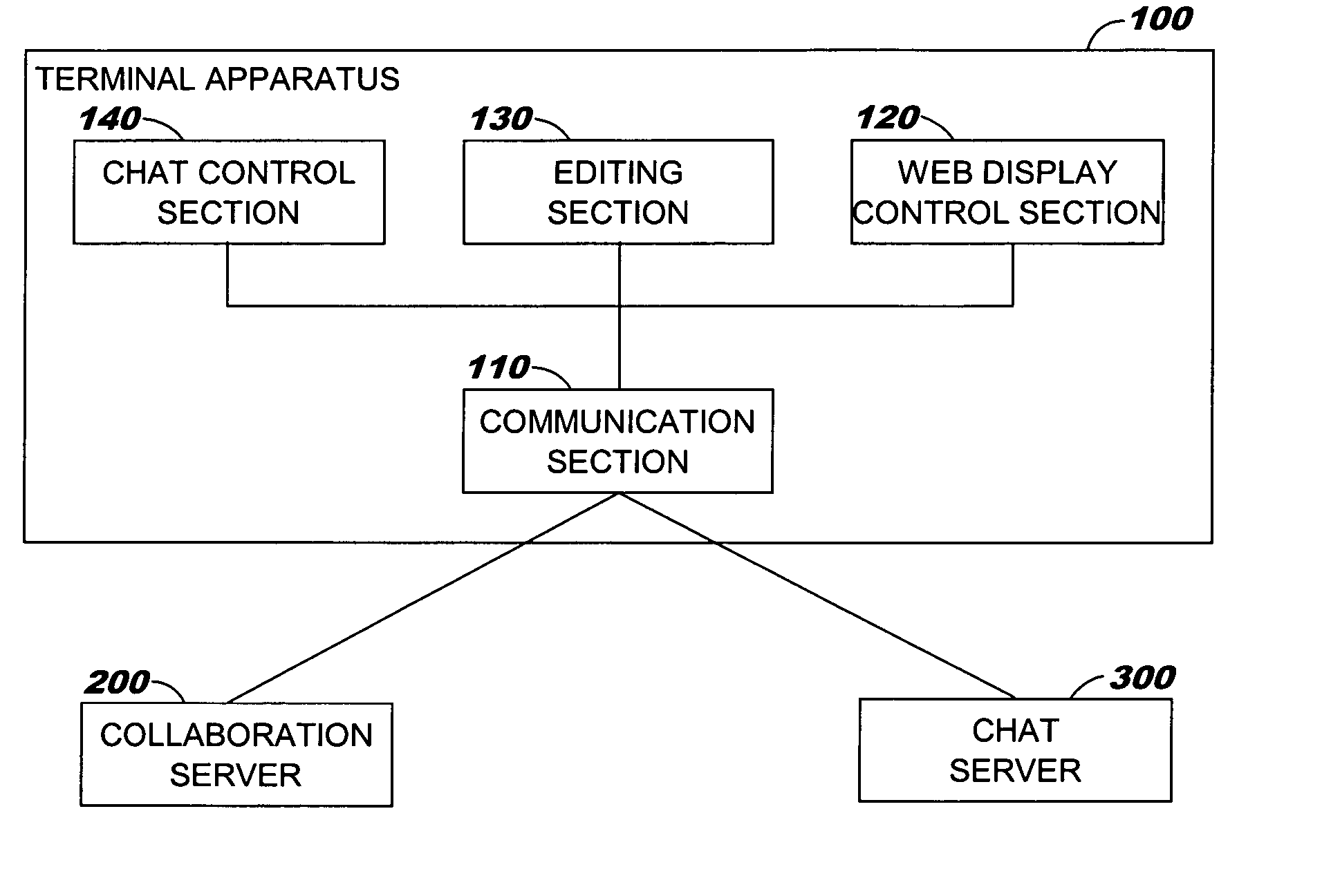
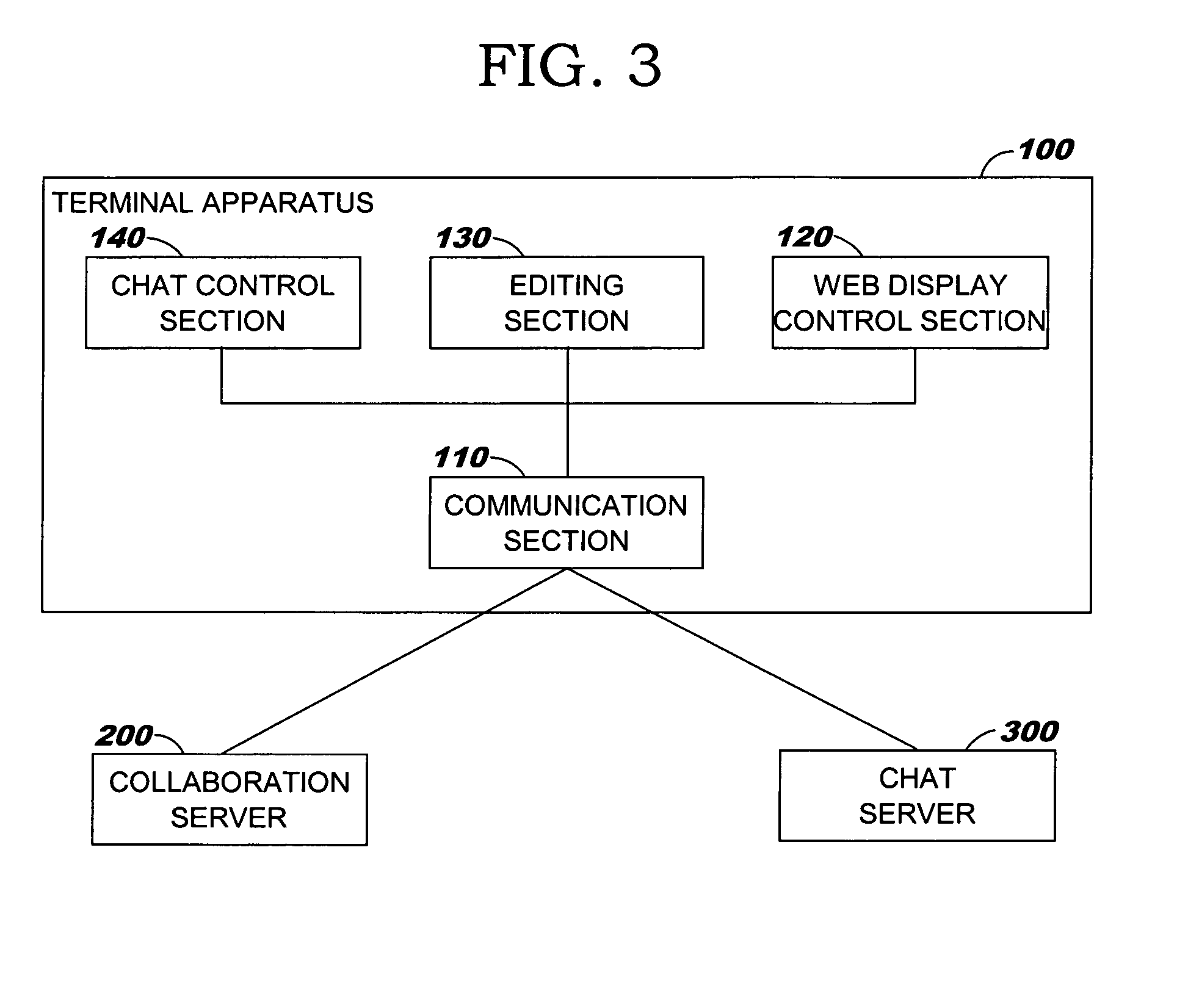
[0036] According to the present invention arranged as described above, a work screen for collaborative work is formed by a Web page to achieve not only a reduction in communication traffic but also control of progress in collaborative work based on operation instructions provided by means of a chat message and on reloading of the Web page. Therefore, a collaboration system and method platform- and OS-independent and having high general versatility can be implemented.

Problems solved by technology

However, the conventional collaboration techniques have problems such as those described below.
In the system in which a display screen image is transmitted and received in the form of a bitmap image to display a common screen image on a plurality of computers, the amount of data communicated as image data to be transmitted and received is large and the load on the network in traffic is increased.
Thus, there is a possibility of hindrance to collaborative work.
Therefore, only limited kinds of OSs are usable in computers utilizing the collaboration system.
For this reason, only limited kinds of Web browsers and OSs are usable.
Also, if only a web page is displayed as a display screen image, it is difficult to clearly show to users participating in collaborative work to which portion of the display screen image a predetermined one of the users is paying attention.
In this conventional art, however, communication between a collaboration server and user terminals is performed in the same manner as communication in other collaboration systems and, therefore, the same problem as that with one of the arts described in the previously-mentioned patent documents, i.e., the problem that only limited kinds of Web browser and OSs are usable or the problem that an execution environment for performing synchronization of the pointer display positions and screen image scrolling by using an anchor tag as a reference mark is required, still remains.

Method used


Image

  • Collaboration server, collaboration system, and method and program for collaboration server and system
  • Collaboration server, collaboration system, and method and program for collaboration server and system
  • Collaboration server, collaboration system, and method and program for collaboration server and system

Examples


Embodiment Construction

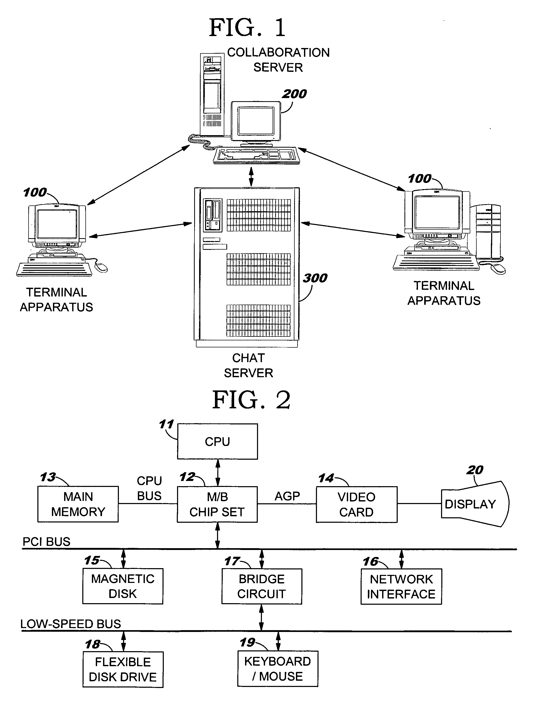
[0057]FIG. 1 is a diagram showing the overall configuration of a collaboration system according to an embodiment of the present invention.

[0058] As shown in FIG. 1, the collaboration system in this embodiment has a plurality of terminal apparatuses 100 for executing collaborative work, a collaboration server 200 which assists collaborative work executed by the terminal apparatuses 100, and a chat server 300 which realizes information exchange among the terminal apparatuses 100 and among the terminal apparatuses 100 and the collaboration server 200 by means of a chat system. The chat server 300, the terminal apparatuses 100, and the collaboration server 200 are connected to each other through a network which is the Internet or the like.

[0059] The collaboration system in this embodiment provides a Web page as a work screen image to be used for collaborative work. In the collaboration system, communication of operation information in collaborative work is performed by a chat. Accordi...


PUM


Abstract

The present invention provides a collaboration system that reduces communication traffic, is platform- and OS-independent, and has high versatility. There are provided a collaboration server connected with a plurality of terminal apparatuses through a network for obtaining, retaining, and distributing a Web page as a work screen used in collaborative work among the terminal apparatuses, and a chat server for managing chat sessions. The collaboration server participates as a chat client in a chat session managed by the chat server and distributes an operation instruction concerning the work screen as a chat message to each terminal apparatus. The work screen is reloaded into each terminal apparatus according to the operation instruction to allow the collaborative work to progress.

Description

BACKGROUND OF THE INVENTION [0001] 1. Field of the Invention [0002] The present invention relates to a collaboration system in which collaborative work is performed by using a plurality of computers connected to a network. [0003] 2. Related Art [0004] Input / output and data processing operations can be synchronized among a plurality of computers connected to each other through a network to enable a common image to be displayed on the displays of the plurality of computers or to enable an input to one of the computers to be reflected in the other computers. Today, collaboration systems which use this technique and in which a plurality of users use a plurality of computers and perform collaborative work by displaying a common work screen image on the displays of the computers are coming into widespread use. [0005] As an example of this kind of collaboration system, a system such as Lotus Sametime from IBM-Lotus is known in which a screen image to be displayed on the displays of compute...

Claims


Application Information

Patent Timeline
IPC IPC(8): G06F3/153G06F13/00G06F15/00G06F15/16G06F17/30H04L29/06
CPCG06Q10/10
Inventor KOMINE, HIROAKIKUSUDA, RIKAMIYAMOTO, MASAKAZU
Owner IBM CORP
Learn More