A common problem of conventional check valves is that upon reversal of liquid flow through tubing in a direction from a patient to a fluid source, the check valves fail to respond as quickly as desired to move into a closed position.
In a procedure, such as a medical
injection procedure, this increases the risk that a check valve may inadvertently be left in an open position.
That is, should such conventional check valves be used, there is always the risk of
backflow from the output to the input of the fluid administration system, which in many instances is very undesirable, and in some cases, may even be fatal.
The normally closed types of fluid check valves used in medical procedures do not allow for the valve to be opened in these instances.
With the standard normally closed check valves in place in current fluid administration systems, backing up the
syringe plunger and thus drawing a fluid, such as blood, through the
catheter and into the delivery tube is impossible.
Another problem with the use of normally closed check valves in a fluid administration system is that some syringes require returning the
plunger to the starting position of an
injector following injection in order for the
syringe to be removed from the
injector.
The removal of the delivery tube has the potential to
expose the medical
technician to biohazards, such as blood or other bodily fluids.
Thus, such a limited
backflow reflux valve, as in the '872 and '074 patents, would not allow the reversal of fluid flow such as would be required to allow a
syringe plunger to be completely backed up within the fluid administration system, such as for subsequent disconnection from an injection system.
Nor does the limited
backflow reflux valve of the '872 and '074 patents allow a fluid to flow in a reverse direction through or past the valve.
Additional problems are raised by these injection procedures.
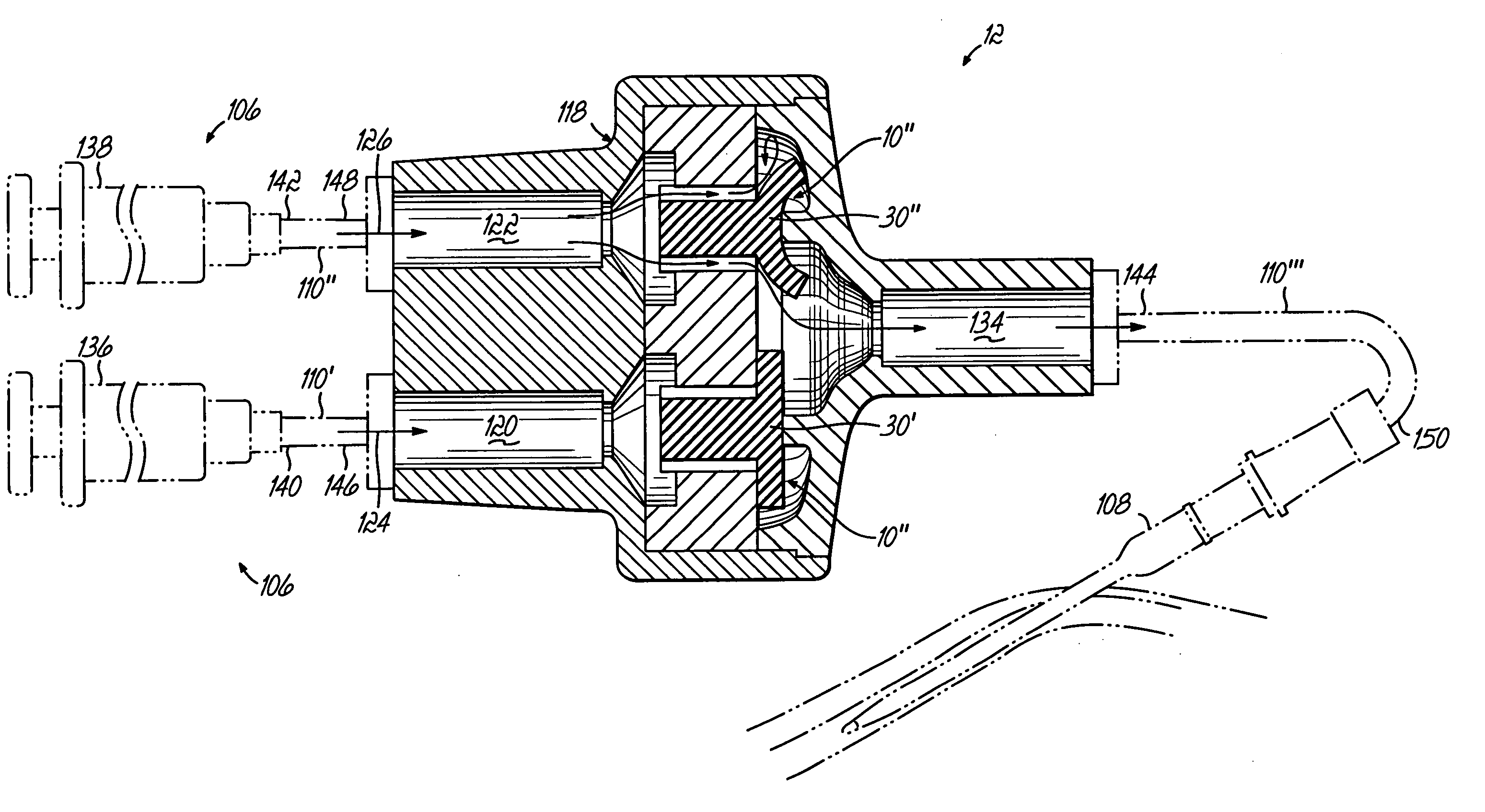
The use of multiple syringes not only increases the possibility of backflow from the output to the input due to the increased number of delivery tubes and syringes, but also includes the additional drawback that a first fluid from a first syringe or first delivery tube may undesirably mix with a second fluid from a second syringe or second delivery tube (or alternatively, that air in a first delivery tube may be introduced into fluid in a second delivery tube, and from there into a patient, with possibly drastic consequences).
Flow turbulence will reduce system performance.
This area may be referred to as a “dead zone.” Since the injection of air is extremely problematic from a patient safety perspective, contrast media is used to remove the air on the
exit side of the check valve by flooding the delivery tubes in proximity to the check valve with contrast media.
Introduction of this contrast media during a pre-scan may alter the final composite image due to false highlighting.
This problem of
image degradation is further compounded by the fact that there are relatively large dead zones in medical injection systems including connectors.
As a result, this relatively large amount of contrast media may be introduced to
saline during a pre-scan, thereby degrading the final image.

