Electronic unit injector with pressure assisted needle control

a technology of electronic unit and fuel injector, which is applied in the direction of fuel injectors, machines/engines, mechanical equipment, etc., can solve the problems of inability to control the fuel pressure of the injector, and inability to do substantial end of injection rate shaping

Active Publication Date: 2005-09-08
CATERPILLAR INC
View PDF13 Cites 16 Cited by
  • Summary
  • Abstract
  • Description
  • Claims
  • Application Information

AI Technical Summary

Benefits of technology

[0006] In one aspect, a fuel injector includes an injector body with a needle valve seat and defines a nozzle chamber, a single nozzle outlet set and a needle control chamber. A one-piece needle valve member is positioned in the injector body and is moveable between a closed position in contact with the needle valve seat to close the single nozzle outlet set, and an open position out of contact with the needle valve seat to open the single nozzle outlet set. The one-piece needle valve member includes a closing hydraulic surface exposed to fluid pressure in the needle control chamber. The one piece needle valve member has an effective opening hydraulic surface area in its open position that is equal to an effective area of the closing hydraulic surface. A biasing spring is positioned in the needle control chamber and is operably coupled to bias the one-piece needle valve member toward its closed position. An electronically controlled pressure control valve is attached to the injector body and has a first position in which the nozzle chamber is fluidly connected to a spill passage, and a second position in which the nozzle chamber is closed to the spill passage. An electronically controlled needle control valve is attached to the injector body and has a first position in which the needle control chamber is fluidly connected to a low pressure passage, and a second position in which the needle control chamber is closed to the low pressure passage. First and second electrical actuators are attached to the injector body and are operably coupled to actuate the electronically controlled pressure control valve and the electronically controlled needle control valve, respectively.
[0007] In another aspect, a method of injecting fuel from a fuel injector includes a step of raising fuel pressure in a nozzle chamber at least in part by energizing a first electrical actuator. A single nozzle outlet set is opened at a selected timing at least in part by positioning a needle control valve at a first position that fluidly connects a needle control chamber to a low pressure passage. The single nozzle outlet set is closed at a selected timing after the opening step using one of at least three available end modes. In a first end mode, the first electrical actuator is de-energized to move the pressure control valve to a first position that opens the nozzle chamber to the spill passage while maintaining the needle control valve in its first position. In a second end mode, pressure forces on the needle valve member are equalized to move the needle valve member toward a closed position with a spring force by moving the needle control valve to a second position that fluidly closes the needle control chamber to the low pressure passage before energizing the first electrical actuator. In a third end mode, the pressure forces on the needle valve member are equalized to move the needle valve member toward its closed position with the spring force by moving the needle control valve to the second position after de-energizing the first electrical actuator.

Problems solved by technology

Over the years, cam actuated fuel injectors have become increasingly complex in a search for ever expanding performance capabilities.
While this fuel injector deletes one electrical actuator, it inherently couples injection timing to fuel pressurization and also suffers from an inability to do substantial end of injection rate shaping, which is more recently becoming recognized as a means by which emissions can be further reduced.
In other words, this injector shows little ability to control the fuel pressure at the timing in which the needle valve closes at the end of an injection event.

Method used


Image

  • Electronic unit injector with pressure assisted needle control
  • Electronic unit injector with pressure assisted needle control
  • Electronic unit injector with pressure assisted needle control

Examples


Embodiment Construction

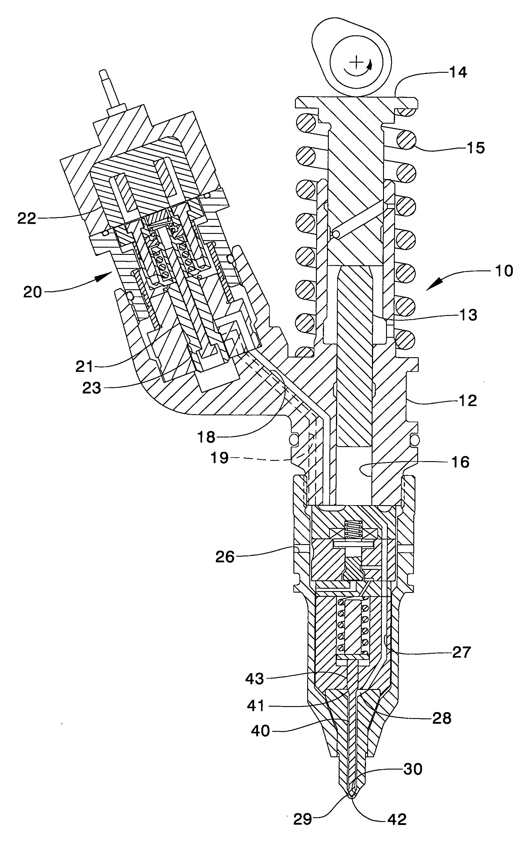
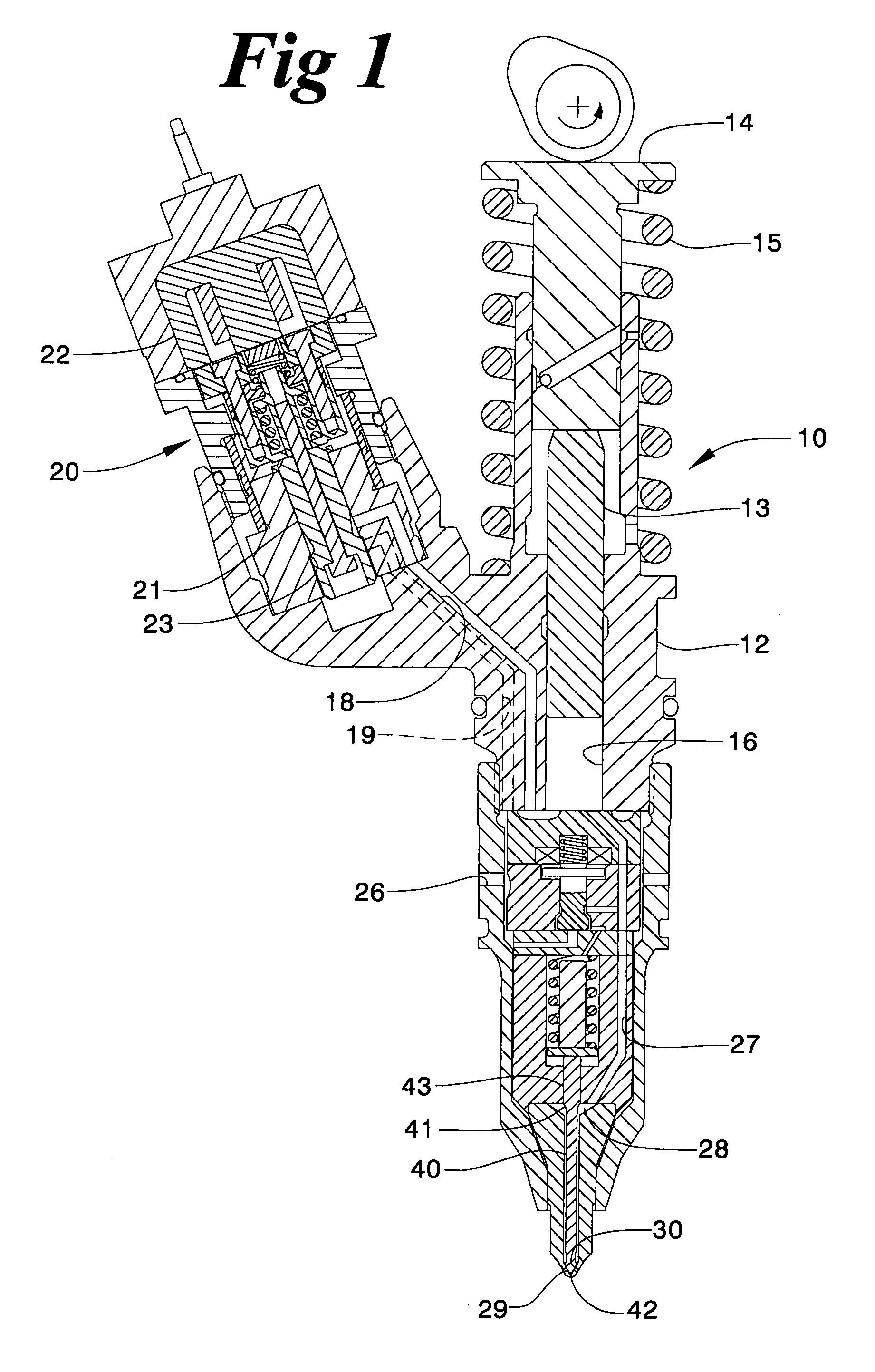
[0013] Referring to FIGS. 1 and 2, a mechanical electronically controlled unit injector 10 includes an injector body 12 that defines a fuel pressurization chamber 16 and a single nozzle outlet set 29. Fuel injector 10 is cam actuated and includes a tappet 14 that slides into injector body 12 to move a plunger 13 in a conventional manner. Tappet 14 includes a surface exposed outside of injector body 12 and is biased to its retracted position, as shown, by a return spring 15. Plunger 13 retracts via a moderate hydraulic force from the fuel supply pressure, which enters at fuel port 26 and is fluidly connected to fuel pressurization chamber 16 via return passage 19 and spill passage 18. When the rotating cam lobe causes tappet 14 to be depressed against the action of return spring 15, plunger 13 is driven downward to displace fluid from fuel pressurization chamber 16 at a relatively low pressure via spill passage 18 and return passage 19. At a desired timing, the fuel can be pressurize...


PUM


Abstract

An electronically controlled fuel injector includes a reduced part count and complexity over similar fuel injectors without a substantial reduction in performance capabilities. This is accomplished by using a one-piece needle that is hydraulically balanced and biased toward a closed position with a spring positioned in the needle control chamber. Although subtle, this injector has some ability to control the fuel pressure when the needle valve is opening and closing by adjusting a relative timing of a pressure control valve opening relative to a needle control chamber, using separate electrical actuators. The invention is particularly applicable to fuel injectors that cycle through high and low pressure states during and between injection events, respectively. Cam actuated fuel injectors being particularly well suited.

Description

TECHNICAL FIELD [0001] The present invention relates generally to electronically controlled fuel injectors, and more particularly to pressure assisted needle control in fuel injectors that cycle through high and low pressure states during and between injection events, respectively. BACKGROUND [0002] Over the years, cam actuated fuel injectors have become increasingly complex in a search for ever expanding performance capabilities. The same is true for other types of fuel injectors including hydraulically actuated and common rail injectors with admission valves. In general, a fuel injection system with a broader range of capabilities is able to increase engine performance while at the same time reducing undesirable exhaust emissions, including particulate matter, unburned hydro-carbons, NOx, etc. One of the first innovations in improving the capabilities of cam actuated fuel injectors was to include an electronically controlled spill valve. This innovation is shown in many prior art ...

Claims


Application Information

Patent Timeline
Patent Type & Authority Applications(United States)
IPC IPC(8): F02M47/02
CPCF02M47/027F02M2547/008F02M59/366F02M57/023
Inventor COLDREN, DANA R.DONG, MINGCHUNHUFFMAN, MICHAEL R.
Owner CATERPILLAR INC
Why Eureka
Try Eureka