Sampling frequency conversion apparatus

Inactive Publication Date: 2005-09-08
SONY CORP
View PDF4 Cites 5 Cited by
  • Summary
  • Abstract
  • Description
  • Claims
  • Application Information

AI Technical Summary

Benefits of technology

[0014] The present invention was accomplished in view of the above-mentioned circumstances, and its object is to easily control the phase difference (time difference) between the input data and the output data in converting the sampling frequency.

Problems solved by technology

However, this kind of conversion into analog signals is inevitably accompanied by a problem of deterioration in the signal characteristics.
When the above ring buffer is used, the writing address and the reading address must be separated away from each other to a certain extent or the buffer does not effectively work.
Therefore, the data of which the sampling frequency is converted involve a delay of timing from when the data is at least written into the buffer until when it is read out.
If the phases of the channels are not correctly set, the sound field is disturbed when the multi-channel audio data are reproduced, which is not desirable.
In order to control the delay time caused by employing the buffer memory to become uniform for all of the channels, a complex control operation is necessary for synchronizing the write and read of the memory for all of the channels, which results in a large-scale constitution of the sampling frequency conversion apparatus.
In such a case, too, a complex operation is required for controlling the writing and reading of the buffer memory.

Method used


Image

  • Sampling frequency conversion apparatus
  • Sampling frequency conversion apparatus
  • Sampling frequency conversion apparatus

Examples


Embodiment Construction

[0024] An embodiment of the present invention will now be described with reference to the accompanying drawings.

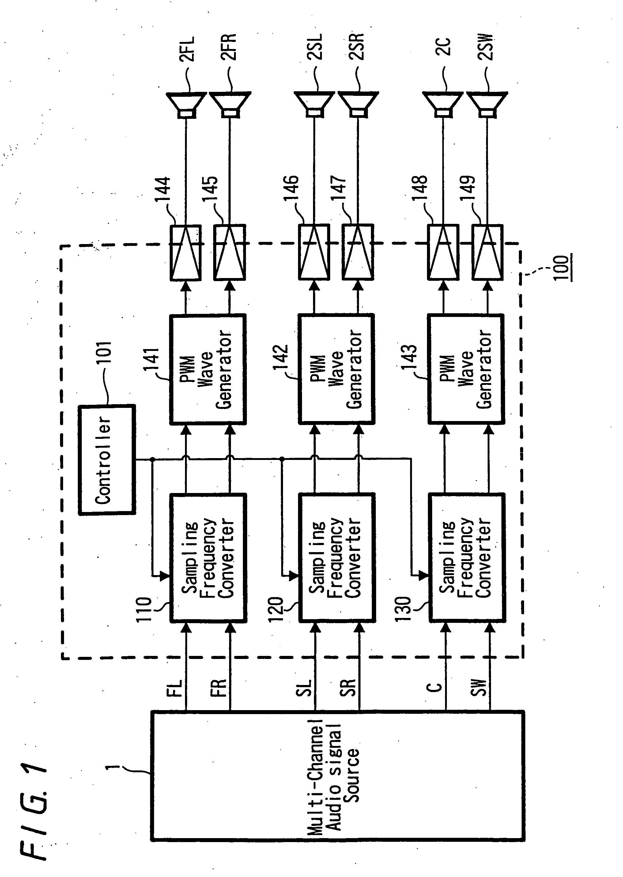
[0025] In this embodiment, the invention is applied to an apparatus that converts the sampling frequencies of audio data of each of the input channels in an audio amplifier apparatus that processes digital audio data of multiplicity of channels. The audio amplifier apparatus of this embodiment is called digital amplifier which forms PWM (Pulse Width Modulation) signals based upon the digital audio data that are supplied, effects the direct switching operation for a predetermined power source relying upon the PWM signals to obtain amplified outputs for driving the speakers.

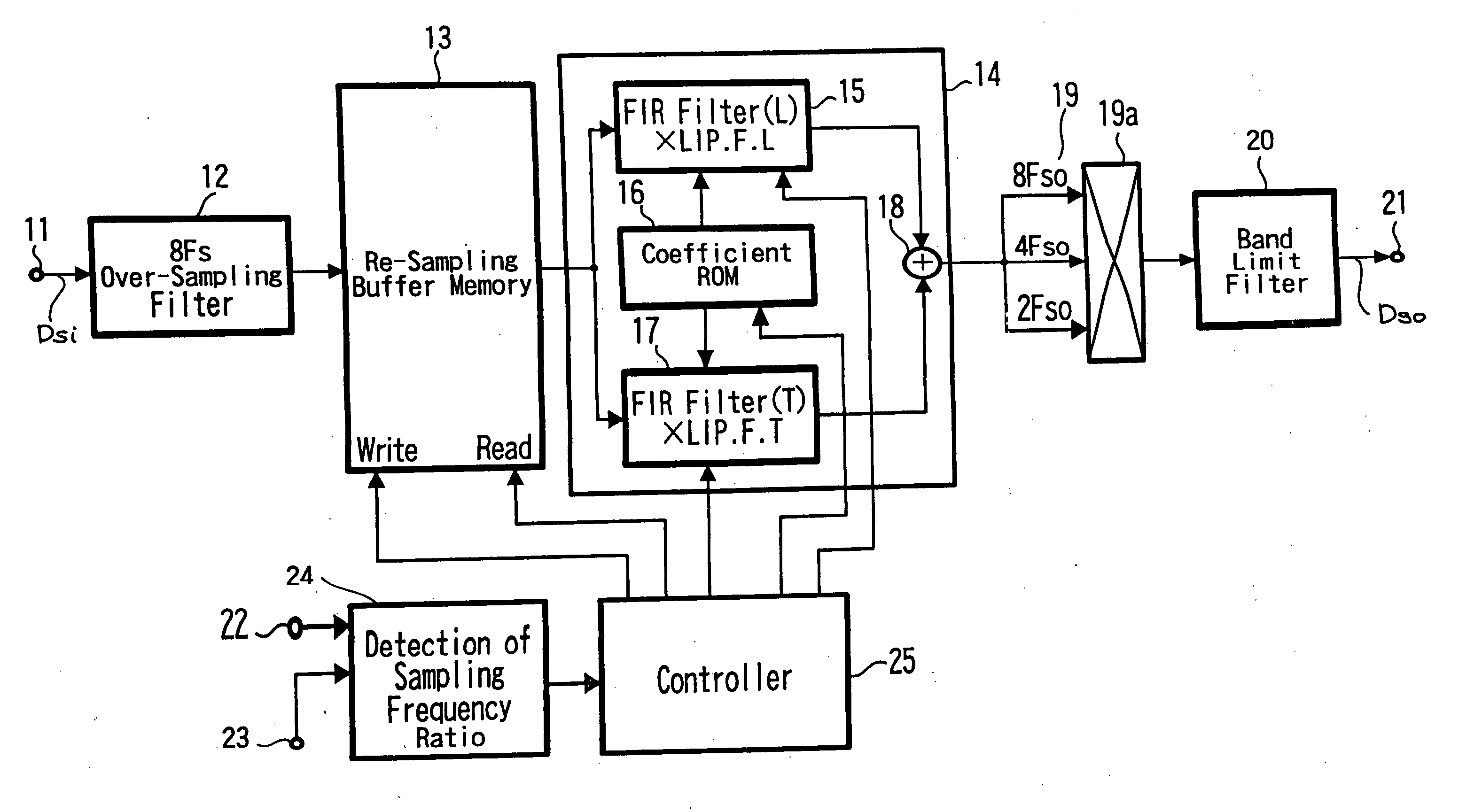
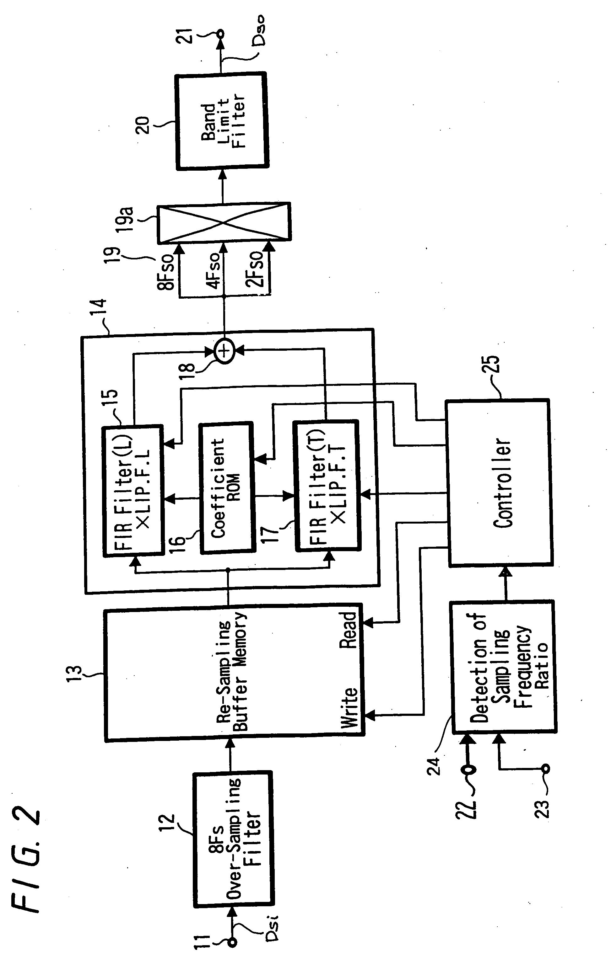
[0026] In this embodiment, the digital audio data for forming the PWM signals in the audio amplifier apparatus must have a particular sampling frequency. The amplifier apparatus is provided with a sampling frequency converter for converting the sampling frequency when the sampling frequency of the digit...


PUM


Abstract

A sampling frequency conversion apparatus which easily controls the phase difference (time difference) between the input data and the output data in converting the sampling frequency, and comprises storage means 13 for continuously writing the input data or the data obtained by over-sampling the input data and for continuously reading out the data written maintaining a predetermined address difference relative to the write address, and interpolation processing means 14 for interpolating the data read out from the storage means 13 to obtain data of which the sampling frequency is converted. In converting the sampling frequency, an address difference between a write address and a read address in the storage means 13 is optimized, the address difference being optimized without limitation for a predetermined period of time from the start of supplying the input data and, then, being optimized by imposing a predetermined limitation after the passage of the predetermined period of time.

Description

BACKGROUND OF THE INVENTION [0001] 1. Field of the Invention [0002] The present invention relates to a sampling frequency conversion apparatus for converting the sampling frequency of digital data such as digital audio data. [0003] 2. Description of Related Art[0004] In recent years, there have been into a practical use a variety of recording media capable of recording digital audio data in a digital form. It is further becoming a common practice to transmit digitized audio data as broadcast data and as data to be transmitted for internet. [0005] Here, the digital audio data are the digitized data obtained by sampling the analog audio signals at a predetermined sampling frequency, and there have been employed a plurality of sampling frequencies. For example, a sampling frequency of 44.1 kHz is used for the digital audio data recorded in an optical disk called compact disk (CD) and for the digital audio data recorded in a magneto-optical disk called mini-disk (MD). The digital audio ...

Claims


Application Information

Patent Timeline
IPC IPC(8): H03H17/00H03H17/06H04B14/02H04B14/04H04H5/00H04H20/89H04L7/02H04L25/05
CPCH03H17/0621H03H17/0628H04L25/05H04H20/89H04B14/026
Inventor YASUDA, NOBUYUKIOHKURI, KAZUNOBU
Owner SONY CORP
Why Eureka
Try Eureka