Utility vehicle

a technology for utility vehicles and vehicles, applied in the field of utility vehicles, can solve the problems that many landscape operations or landscapers cannot use large motor operated vehicles, and the use of such large, motor operated vehicles may be prohibited, so as to reduce damage to the ground surface or the area

Inactive Publication Date: 2005-09-08
GREEN KEVIN J
View PDF7 Cites 14 Cited by
  • Summary
  • Abstract
  • Description
  • Claims
  • Application Information

AI Technical Summary

Benefits of technology

[0009] The loading apparatus or system may include a unique foot and fork assembly that, once attached to the utility vehicle, provides an apparatus that can lift and load items in excess of the weight of the vehicle onto the vehicle.
[0010] The present invention further provides a utility vehicle of a size and design suitable to operate in confined or small spaces with a propulsion system that reduces damage to the ground surface or area in which the vehicle is operating. The vehicle has the ability to be operated by a single operator. Further, the present invention may include a lift and load apparatus attached to the utility vehicle wherein the utility vehicle has the ability to load and unload materials or items as well as being able to drag or carry these materials or items.

Problems solved by technology

Further, they provide assistance when working in and around areas that cannot be easily reached by larger motor operated vehicles, particularly in areas too small or confined to allow the operation of such vehicles.
For instance, many landscape operations or landscapers cannot use large motor operated vehicles when working around homes or other structures, especially in developed areas where such vehicles will not fit or cannot be maneuvered due to the confines created by home density, fences and landscapes.
Further, use of such large, motor operated vehicles may be prohibited due to the damage such vehicles would cause to the landscape.

Method used


Image

  • Utility vehicle
  • Utility vehicle
  • Utility vehicle

Examples


Embodiment Construction

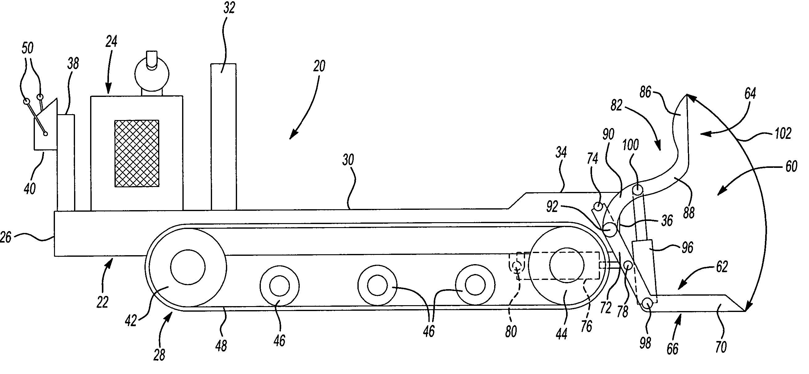
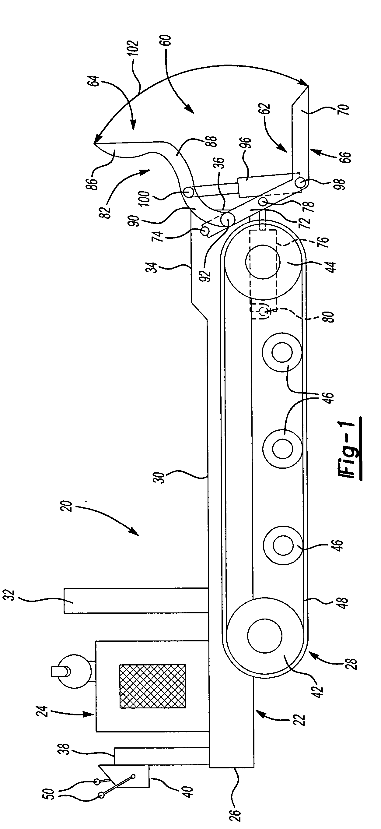
[0022] Turning now to FIG. 1, a utility vehicle 20 is shown, according to one embodiment of the present invention. The utility vehicle 20 includes a vehicle frame, seen generally at 22. A power source 24, typically an internal combustion engine or an electric motor, is secured to the vehicle frame 22 near the rear end 26 of the vehicle frame 22. A propulsion system, seen generally at 28, is attached to the vehicle frame 22 and operates, upon receiving power through a drivetrain (not shown), to propel the utility vehicle 20.

[0023] A platform or bed 30 is attached to the upper surface of the vehicle frame 22. The bed or platform 30 forms a load-carrying surface of the utility vehicle 20. A first barrier member or wall 32 extends upwardly from the platform or bed 30 and forms a load-containing surface located adjacent the power source 24. As shown in FIG. 1, the platform or bed 30 may include a small upwardly extending raised portion or stop 34 located at the front end 36 of the utili...


PUM


Abstract

A versatile mobile utility cart or vehicle using either tracks, wheels or both for suspension and steering with propulsion coming from but not limited to an internal combustion engine or an electric motor. The vehicle is meant to be a utility workhorse with the ability to load and unload itself as well as drag or carry materials. The vehicle can be configured in many ways to do many tasks with the main feature being labor savings. One of the unique features of the vehicle is a loading system called a fork and foot system. For transport the forks and feet system can be raised or detached individually or as a system, this is beneficial when unloading. The foot may remain attached and used for stability. Detaching the fork and foot system as a system allows the vehicle to be used for other tasks including but not limited to: a dump vehicle; a skidder; a reel carrier; a fork lift/carrier; and a prime mover or base for brush chippers, stump cutters, tree spades and more.

Description

CROSS-REFERENCE TO RELATED APPLICATIONS [0001] This application claims the benefit of U.S. Provisional Application No. 60 / 546,008, filed Feb. 19, 2004.BACKGROUND OF THE INVENTION [0002] 1. Field of the Invention [0003] The present invention relates generally to a mobile utility vehicle for loading, transporting and unloading materials. In addition, the utility vehicle also includes a unique loading apparatus. [0004] 2. Description of Related Art [0005] Utility vehicles such as handcarts, hand trucks, wheelbarrows and other devices have been used for many years as labor saving devices. These devices assist an individual or laborer in performing manual labor such as moving and transporting objects and workpieces. Further, they provide assistance when working in and around areas that cannot be easily reached by larger motor operated vehicles, particularly in areas too small or confined to allow the operation of such vehicles. [0006] For instance, many landscape operations or landscaper...

Claims


Application Information

Patent Timeline
Patent Type & Authority Applications(United States)
IPC IPC(8): B60P9/00
CPCB60P1/28B60P3/42B60P3/035
Inventor GREEN, KEVIN J.
Owner GREEN KEVIN J
Why Eureka
Try Eureka