Electronically controlled vacuum pump

a vacuum pump and electric motor technology, applied in the direction of piston pumps, positive displacement liquid engines, separation processes, etc., can solve the problems of affecting the operation the gas as being pumped by the turbomolecular pump may be extremely corroded or hazardous, etc., to facilitate the enhancement of individual pumps, improve the efficiency of the vacuum pump, and reduce the burden on the central computer

Inactive Publication Date: 2005-09-08
BROOKS AUTOMATION INC
View PDF48 Cites 36 Cited by
  • Summary
  • Abstract
  • Description
  • Claims
  • Application Information

AI Technical Summary

Benefits of technology

[0023] The electronic control module may control shutdown of the vacuum system by turning off power to the drive motor and opening the vent valve. Only subsequently is the roughing valve closed. By thus closing the roughing valve only after the vent valve has been opened, there can be no back streaming of gases through the turbomolecular pump as the pump slows down. By introducing the vent gas into a midsection of the rotor, potential damage to the bearings with the prompt pressure change is avoided. A delay of a few seconds between opening of the vent valve and closing of the roughing valve is preferred.
[0027] Individual and local electronic control of each vacuum pump has many advantages over strictly central and remote control Although the present system has the advantage of being open to control and monitoring from a remote central station, control of any pump is not dependent on that central station. Therefore, but for a power outage, it is much less likely that all pumps in a system will be down simultaneously. The local storage of data such as calibration data and data histories are readily retained in the local memory without requiring any access to the central station. Thus, for example, in servicing a vacuum by replacing a module, the service person need not input any new data into the central computer because all necessary information is retained and set at the pump itself. Also, in servicing a pump, it is much more convenient to the service person to have full control of the pump when he is at the pump itself rather than having to seek control through a remote computer. The local full control of the vacuum facilitates enhancements to individual pumps because there is no burden on the central computer. As a result, many procedural improvements which provide faster, more thorough regeneration are more likely to be implemented. The removable module greatly facilitates servicing of the unit, and the battery-backed memory allows such servicing without loss of data. The module also facilitates upgrading of any individual pump.

Problems solved by technology

Thermocouple pressure gauges have also been used with cryopumps but have generally not been recommended because of a potential of igniting gases released in the cryopump by a spark from the current-carrying thermocouple.
Because the gas as being pumped by the turbomolecular pump may be extremely corrosive or hazardous in other ways, it is often diluted by a purge gas in the foreline region of the pump.

Method used


Image

  • Electronically controlled vacuum pump
  • Electronically controlled vacuum pump
  • Electronically controlled vacuum pump

Examples


Embodiment Construction

[0051] A description of preferred embodiments of the invention follows.

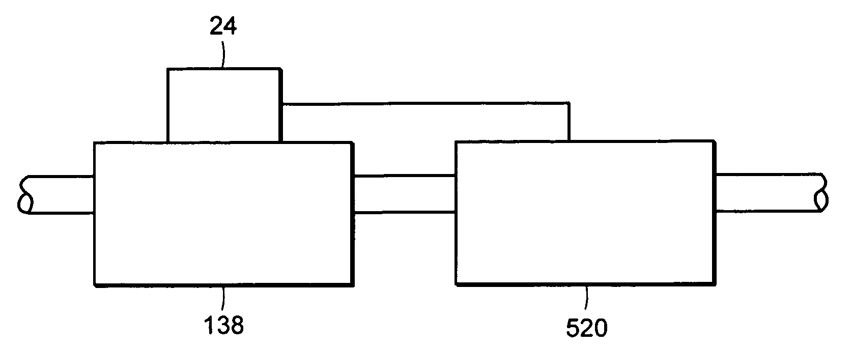
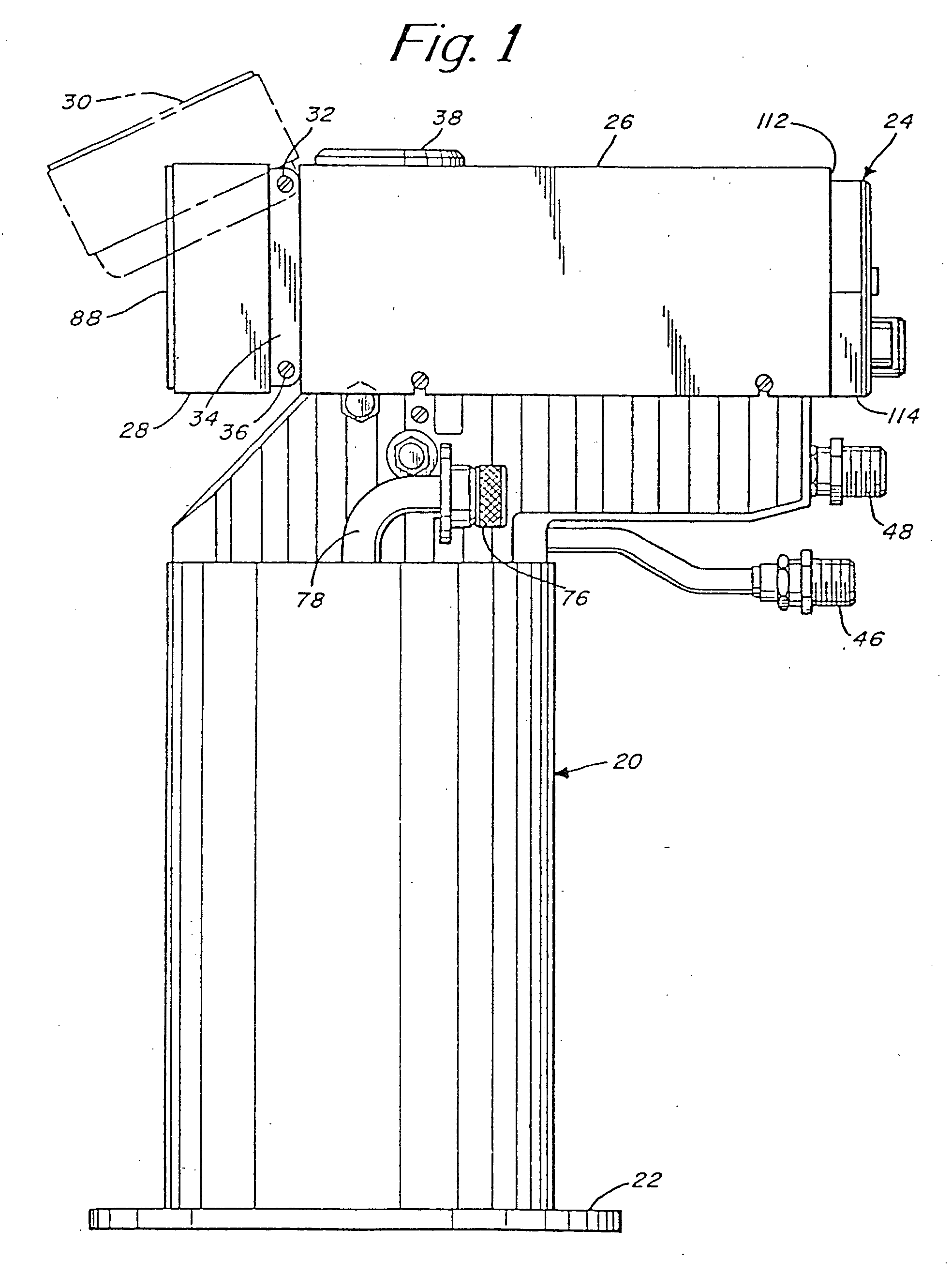
[0052]FIG. 1 is an illustration of a cryopump embodying the present invention. The cryopump includes the usual vacuum vessel 20 which has a flange 22 to mount the pump to a system to be evacuated. In accordance with the present invention, the cryopump includes an electronic module 24 in a housing 26 at one end of the vessel 20. A control pad 28 is pivotally mounted to one end of the housing 26. As shown by broken lines 30, the control pad may be pivoted about a pin 32 to provide convenient viewing. The pad bracket 34 has additional holes 36 at the opposite end thereof so that the control pad can be inverted where the cryopump is to be mounted in an orientation inverted from that shown in FIG. 1. Also, an elastomeric foot 38 is provided on the flat upper surface of the electronics housing 26 to support the pump when inverted.

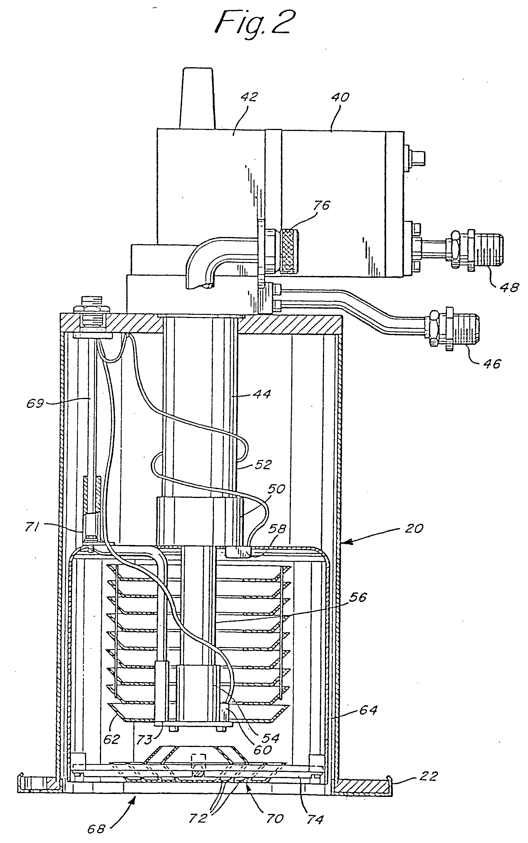
[0053] As illustrated in FIG. 2, much of the cryopump is conventional. In FIG. 2, the ho...


PUM

PropertyMeasurementUnit
temperatureaaaaaaaaaa

Abstract

A vacuum system comprises, as an integral assembly, a vacuum pump with drive motor, a purge valve, a roughing valve and an electronic control module. A cryogenic vacuum pump and a turbomolecular vacuum pump are disclosed. The control module has a programmed processor for controlling the motor and valves and is user programmable for establishing specific control sequences. The integral electronic control module is removable from the assembly and is connected to the other devices through a common connector assembly. In the turbomolecular pump system proper introduction of a purge gas through the purge valve is detected by detecting the current load on the pump drive or by detecting foreline pressure. To test the purge gas status, the purge valve may be closed and then opened as drive current or pressure is monitored. After power failure, the controller will continue normal drive of the turbomolecular pump so long as the speed of the pump has remained above a threshold value. Otherwise the vent valve will have been opened, and a start-up sequence must be initiated. During shutdown, power to the pump drive motor is discontinued and the vent valve is opened before the roughing valve is closed.

Description

RELATED APPLICATIONS [0001] This application is a divisional of U.S. application Ser. No. 10 / 095,126, filed Mar. 8, 2002, which is a continuation of U.S. application Ser. No. 09 / 454,358, filed on Dec. 3, 1999, which is a continuation of U.S. application Ser. No. 08 / 517,091, filed Aug. 21, 1995, which is a Continuation-in-Part of U.S. application Ser. No. 08 / 092,692, filed Jul. 16, 1993, now U.S. Pat. No. 5,443,368, the entire teachings of which are incorporated herein by reference.BACKGROUND OF THE INVENTION [0002] Vacuum systems often comprise a main vacuum pump which is driven by a drive motor and associated with various sensors, valves and other peripheral devices. The main vacuum pump may also be associated with a vacuum roughing pump and a secondary pump for specific gases such as water vapor. Cryopumps and turbomolecular pumps, for example, generally include temperature and pressure sensors and purge and roughing valves. A turbomolecular pump may also be associated with a cryo...

Claims


Application Information

Patent Timeline
Patent Type & Authority Applications(United States)
IPC IPC(8): F04B37/08F04B49/06F04D19/04F04D27/00
CPCF04B37/08F04D27/00F04D19/04F04B49/065Y10S417/901F04D15/0066
Inventor GAUDET, PETER W.LEPOFSKY, ROBERT J.WEEKS, ALAN L.FORTIER, GERALD J.MATTE, STEPHEN R.STEIN, MARTINROSNER, STEVEN C.
Owner BROOKS AUTOMATION INC
Why Eureka
Try Eureka