
System and method for designing a physiometric implant system

a technology of physiometric implants and design systems, applied in the field of implant design systems, can solve the problems of increasing the cost of fabrication, deteriorating one or more joint compartments, and affecting the quality of life of the implant, and achieve the effect of reducing the conditional parameter

Active Publication Date: 2005-09-08
DEPUY PROD INC
View PDF47 Cites 166 Cited by
  • Summary
  • Abstract
  • Description
  • Claims
  • Application Information

AI Technical Summary

Benefits of technology

[0011] The conditional parameter may be motion interference, economy of motion, reduction of jerk, normality of ligament tension, evenness of load sharing, minimization of energy consumption, path matching of motion, limited motion envelope, dynamic stability, reduced sensitivity to a change such as soft tissue injury or degradation, avoidance of stress peaks, controlled stress pattern, improved bone growth response, and optimal fitting. A conditional parameter for a kinematic simulation may incorporate one or more of these parameters.
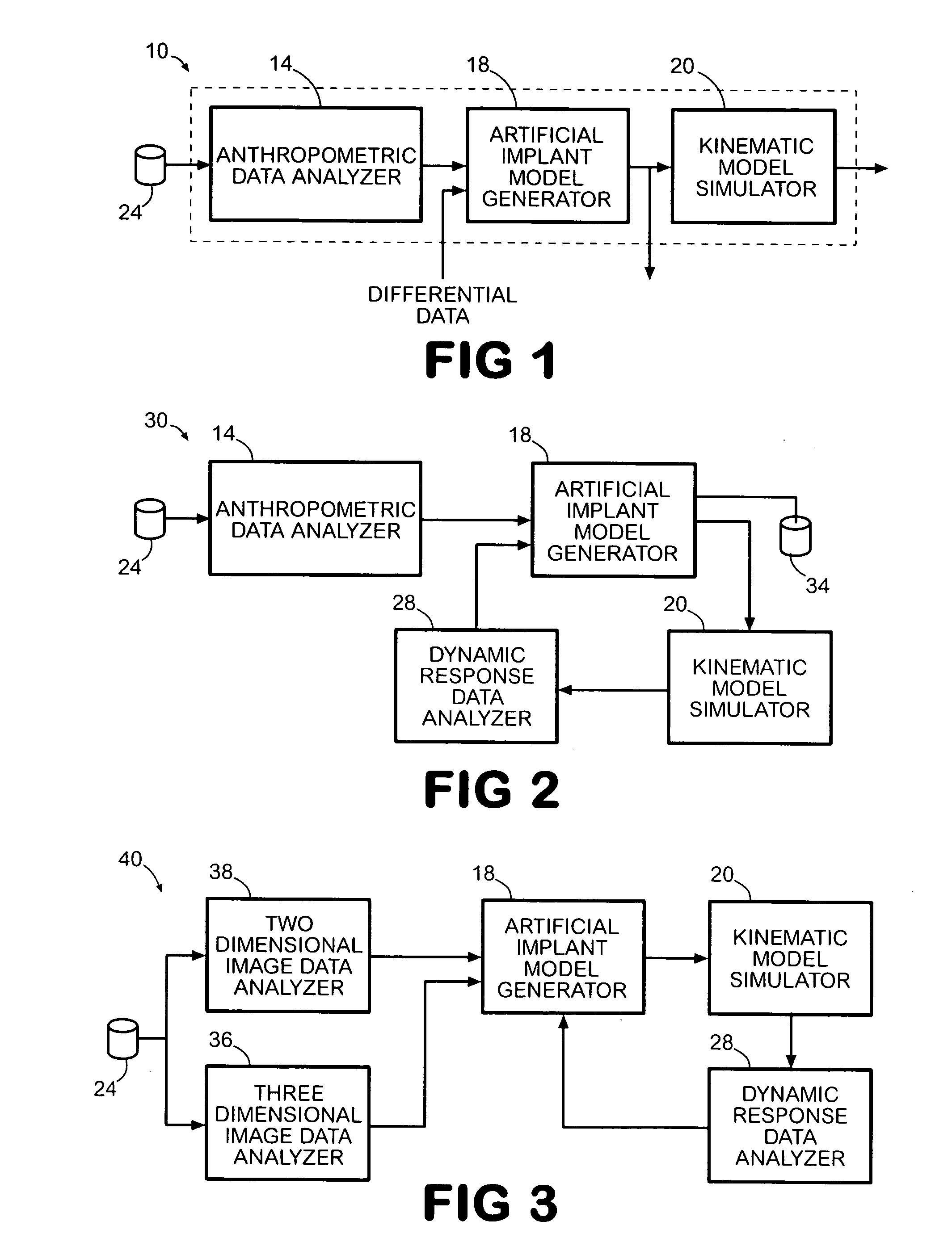
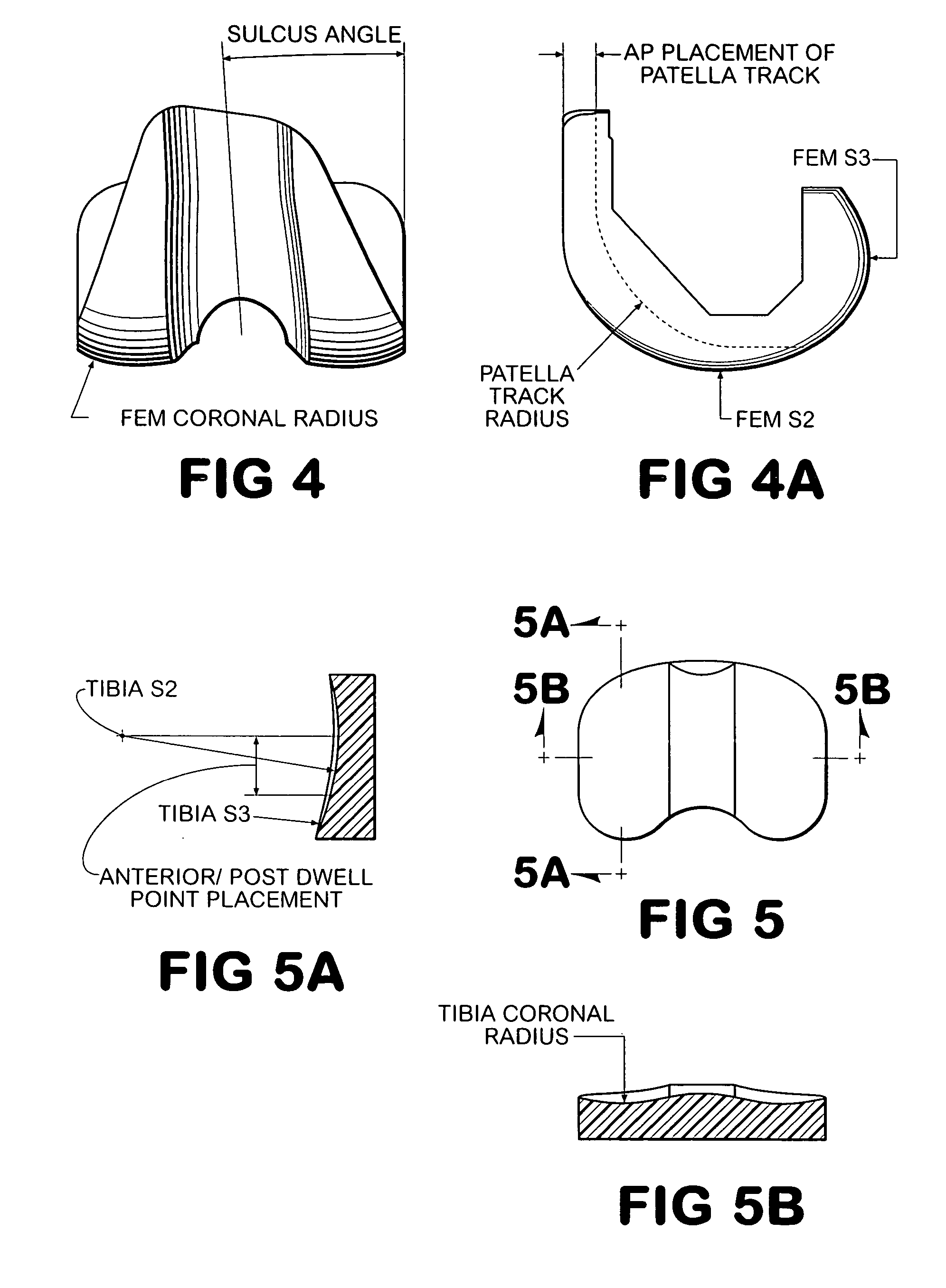
[0014] To further adapt an implant model to particular patient geometries, the implant model generator may use fluoroscopic or other dynamic image data for a plurality of patient joints in dynamic motion. These data may be used to verify that a set of model data generated by the implant model generator enables the components of the joint to move without causing a conditional parameter. If an undesired conditional parameter occurs, dimensional adjustments may be made to the implant model to reduce the likelihood that the conditional parameter occurs. For example, fluoroscopic data may be compiled by taking fluoroscopic X-ray images of one or more patient joints in motion. These images are two dimensional images of the relationship between joint components as the joint is moved. The implant model generator maps that dynamic response data into a set of positions for the components corresponding to the set of model data. This enables the implant model generator to determine whether the dimensions represented by the set of model data need modification to attenuate a conditional parameter that appears likely when the model components are in one of the relationships depicted in the dynamic response data. The set of model data generated by the model generator may be used to fabricate a solid model of an artificial implant component that corresponds to the geometric dimensions and measurements of the model data set. However, the system of the present invention also includes the kinematic model simulator for generating a more robust set of dynamic response data so that the dynamic response of the model data may be better evaluated. Furthermore, as explained in more detail below, the fluoroscopic data may be used to generate a patient model simulator for generating emulation force parameters for the kinematic model simulation.
[0016] These dynamic response data may be used to evaluate the motion of the joint components as a function of time during various joint movements. Such evaluations enable implant designers to obtain a likely view of how the implant components will move within the joint following replacement surgery. The simulation of the joint with the implant model enables the designers to see whether the implant supports a normal range of motion and whether adjustments need to be made in the positioning of the implant in the joint for proper joint movement. Identification of a conditional parameter may be used to generate a set of differential dimensional data to alter the set of model data so the conditional parameter may be reduced. Because the differential data may result in changes in the dynamic response data at other positions, the differential data are incorporated in the implant model data by the implant model generator to generate another set of model data for evaluation. By repeating the process, model modifications may be more fully evaluated for fit throughout a range of motion for a joint.
[0017] A method that operates in accordance with the principles of the present invention analyzes anthropometric static image data to generate a plurality of geometric dimensions and a range of dimension measurements, generates a set of implant model data from the plurality of geometric dimensions and the range of dimension measurements, simulates kinematic motion of a joint with the set of implant model data to generate dynamic response data representative of artificial implant component movement within a reconstructed joint. The method may also generate differential data in response to dynamic response data that indicates a conditional parameter occurs in at least some portion of the simulated kinematic motion of the joint. The generation of the set of model data may also include incorporating positional data from images of a joint in motion, such as fluoroscopic images of the joint in motion. These data of a joint in motion may be used to verify the dimensions of the implant model. Additionally, the inclusion of the positional data in the form of the fluoroscopic data reduces the likelihood that the set of model data modified by the differential data only conforms to the joint emulated by the kinematic simulator.
[0021] The system and method of the present invention improve the likelihood that an artificial implant component will not interfere with the smooth operation of articulating surfaces of artificial implants and will cooperate with a patient's ligament and musculature.

Problems solved by technology

Bone disease, such as arthritis, may deteriorate one or more joint compartments so that movement in the joint produces pain.
However, customizing every artificial implant component for a replacement surgery would significantly increase the cost of fabrication and coordination of component production with surgical resources would be difficult.
One problem with this approach is the fit required for a complete range of motion for the joint.

Method used


Image

  • System and method for designing a physiometric implant system
  • System and method for designing a physiometric implant system
  • System and method for designing a physiometric implant system

Examples


Embodiment Construction

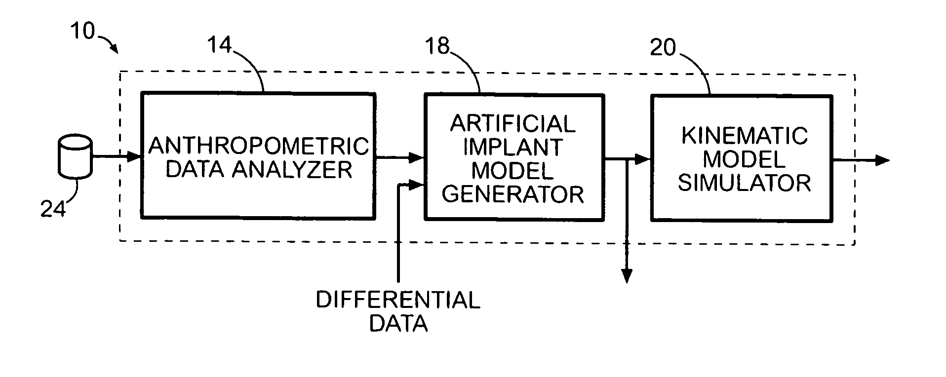
[0039] A system 10 for generating model data to fabricate an artificial implant component for a joint reconstruction is shown in FIG. 1. The system 10 includes an anthropometric data analyzer 14, an artificial implant model generator 18, and a kinematic model simulator 24. The anthropometric data analyzer 14 receives static image data, such as CT data, from a database 24. Preferably, the anthropometric data analyzer 14 performs a frequency distribution analysis on the static image data to generate one or more groupings of geometric dimensions and dimensional measurement ranges that are provided to artificial implant model generator 18. Preferably, artificial implant model generator 18 uses at least one grouping of geometric dimensions and measurement ranges to generate an implant model data set that may be used to fabricate a solid model of an artificial implant.

[0040] The kinematic model simulator 20 of the system 10 is a computer program that simulates a joint in dynamic motion. ...


PUM


Abstract

A system improves the design of artificial implant components for use in joint replacement surgeries. The system includes an anthropometric static image data analyzer, an implant model data generator, a kinematic model simulator, and a dynamic response data analyzer. The implant model data generator may also use image data of a joint in motion for modification of the implant model data used in the kinematic simulation. Dynamic response data generated by the kinematic model simulation is analyzed by the dynamic response data analyzer to generate differential data that may be used to further refine the implant model data.

Description

CLAIM OF BENEFIT OF PRIORITY [0001] This application claims the benefit of priority under 35 U.S.C. 119(e) from Provisional Patent Application entitled System and Method for Designing a Physiometric Implant System, filed on Mar. 5, 2004, and assigned Ser. No. 60 / 550,713.FIELD OF THE INVENTION [0002] This invention relates to implant design systems and, more particularly, to systems for designing implants for joint replacement surgeries. BACKGROUND OF THE INVENTION [0003] Joints in the body have compartments with articulating surfaces that move against or in close proximity with other components in the joint. For example, the knee joint includes the distal femur that cooperates with both the patella and proximal tibia and, if present, a fabella. The distal femur has a lateral and medial condyle that rotates in moving relationship to the lateral and medial meniscus of the tibia. Bone disease, such as arthritis, may deteriorate one or more joint compartments so that movement in the joi...

Claims


Application Information

Patent Timeline
IPC IPC(8): A61F2/30A61F2/38G06G7/48
CPCA61B2019/502A61F2/30942A61F2002/30952A61F2/3877A61F2002/30948A61F2/38A61B2034/102
Inventor ARAM, LUKE J.AUGER, DANIELLEE, JORDAN S.HAYDEN, ADAM I.
Owner DEPUY PROD INC
Learn More