Pressure-temperature control for a cryoablation catheter system

a technology of cryoablation and temperature control, which is applied in the direction of catheters, domestic cooling devices, container discharge methods, etc., can solve the problems of reducing the efficiency of cryoablation, serious safety concerns, and unable to produce the larger lesions needed, so as to achieve greater resistance, facilitate the effect of achieving the effect of ablation and greater pressure drop

Inactive Publication Date: 2005-09-15
CRYOCOR
View PDF63 Cites 17 Cited by
  • Summary
  • Abstract
  • Description
  • Claims
  • Application Information

AI Technical Summary

Benefits of technology

[0009] In operation, the fluid refrigerant is introduced into the supply tube in a liquid state at a working pressure “pw”. Typically the working pressure “pw” will be controlled to be in a range between three hundred and fifty psia and five hundred psia (350-500 psia). The liquid refrigerant then sequentially transits through the supply tube and the capillary tube. As specifically intended for the present invention, the fluid refrigerant experiences much more resistance, and a much greater pressure drop, as it passes through the capillary tube than while passing through the supply tube.
[0010] Importantly, as the fluid refrigerant exits the distal end of the capillary tube, it is substantially still in a liquid state. The dimensions of both the supply tube and capillary tube are specifically chosen, and the working pressure “pw” is actively controlled, to facilitate this result. The tip pressure “pt” on the fluid refrigerant, as it enters the cryo-chamber, is preferably less than about one atmosphere. As a result of the decrease in pressure to less than one atmosphere, the liquid refrigerant will begin to boil in the cryo-chamber, transitioning from a liquid state to a gaseous state. After the fluid refrigerant has transitioned into its gaseous state, the measured temperature, and hence the tip temperature “Tt”, will be at a minimum, and preferably less than about minus eighty-four degrees Centigrade (pt<−84° C.).
[0011] For a capillary tube having a known length and diameter, a curve can be plotted showing the tip temperature “Tt” (y-axis) as a function of working pressure “pw” (x-axis). There is a region of the pressure-temperature curve where the fluid refrigerant transitions from a liquid state to a gaseous state. This transition region is characterized by a pronounced change in the slope of the curve. As can be understood by those skilled in the art, the slope may be defined as the change in

Problems solved by technology

Recently it has become apparent that RF energy is not ideal for producing the larger lesions needed to treat complex arrhythmias such as atrial fibrillati

Method used


Image

  • Pressure-temperature control for a cryoablation catheter system
  • Pressure-temperature control for a cryoablation catheter system
  • Pressure-temperature control for a cryoablation catheter system

Examples


Embodiment Construction

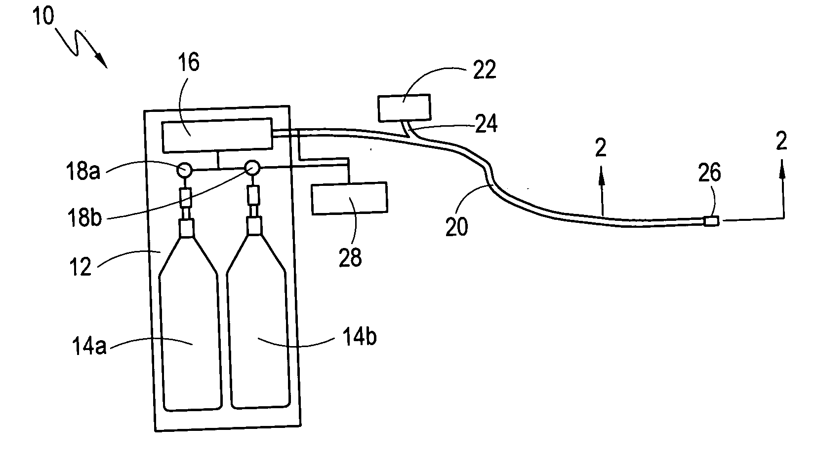
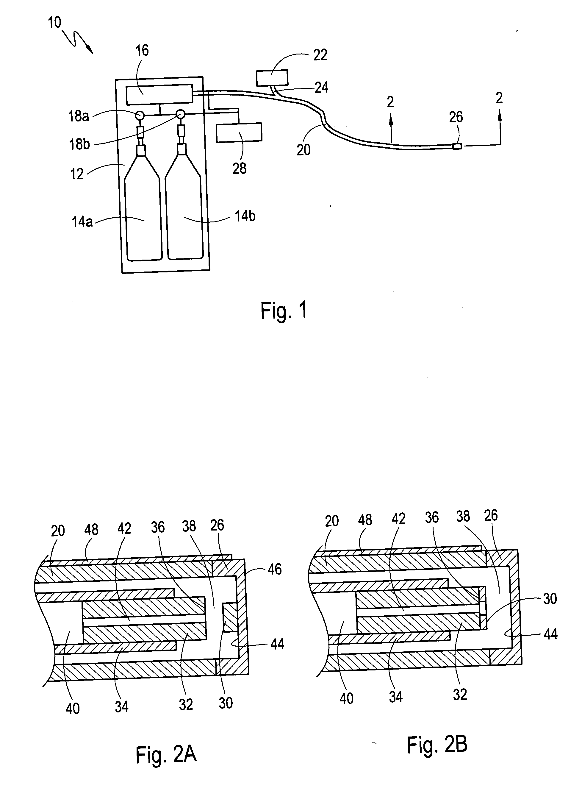
[0018] A system in accordance with the present invention is shown in FIG. 1 and is generally designated 10. In detail, the system 10 includes a console 12, inside of which are mounted two fluid refrigerant sources 14a and 14b. The fluid refrigerant sources 14a and 14b shown in FIG. 1 are, however, only exemplary. As contemplated for the present invention, the fluid refrigerant sources 14a and 14b may be any type pressure vessel known in the pertinent art that is suitable for holding and subsequently dispensing a fluid under relatively high pressures (e.g. 700 psi). Positioned between the fluid refrigerant sources 14a and 14b and a pre-cooler 16, are pressure regulators 18a and 18b. In operation, fluid refrigerant flows out of the fluid refrigerant sources 14a and 14b, through the pressure regulators 18a and 18b, and into the pre-cooler 16, where it is cooled. For the purposes of the present invention, the preferred fluid refrigerant is nitrous oxide (N2O).

[0019] Still referring to ...


PUM


Abstract

A heat transfer system and method for cryoablation includes a cryo-catheter with a tip, and a temperature sensor mounted at the distal end of the cryo-catheter. A system controller is in electronic communication with both a pressure regulator and the temperature sensor. The system takes advantage of the transfer of latent heat to minimize the tip temperature at the distal end of the cryo-catheter. More specifically, after measuring the temperature at the distal end of the cryo-catheter, and comparing the temperature data and input pressure to a known pressure-temperature curve, the input pressure of the liquid fluid refrigerant may be adjusted. At the correct pressure setting, the liquid fluid refrigerant will begin to boil at the distal end of the cryo-catheter, and the tip temperature will be at a minimum.

Description

FIELD OF THE INVENTION [0001] The present invention pertains generally to interventional medical devices. More particularly, the present invention pertains to cryo-catheters that are used to ablate tissue in the vasculature of a patient. The present invention is particularly, but not exclusively useful as a device and method for measuring the tip temperature at the distal end of a cryo-catheter and using the temperature data to control, as necessary, the input pressure of the fluid refrigerant. BACKGROUND OF THE INVENTION [0002] Catheter ablation procedures have been clinically available for many years. The typical procedure involves passing radiofrequency (RF) electrical energy through a catheter, thereby heating and subsequently cauterizing or burning the tissue. Recently it has become apparent that RF energy is not ideal for producing the larger lesions needed to treat complex arrhythmias such as atrial fibrillation. With larger lesions, the standard approach of using RF energy m...

Claims


Application Information

Patent Timeline
IPC IPC(8): A61B18/02A61B18/18F17C7/02F17C9/02F25B1/00F25B19/02F25D3/10F25D29/00
CPCA61B18/02F25D29/001A61B2018/0262A61B2018/0212
Inventor LENTZ, DAVID J.RIORDAN, MATT M.
Owner CRYOCOR
Why Eureka
Try Eureka