Error adjustment for multi-antenna transmitter

a multi-antenna transmitter and error adjustment technology, applied in multi-frequency code systems, multiplex communication, orthogonal multiplexes, etc., can solve the problem of inaccuracy of frequency selective iq phase and amplitude imbalance, the inability to accurately adjust the error, and the inability to use expensive and precise filters. problem, to achieve the effect of improving signal accuracy, reducing analog filter requirements, and improving error adjustmen

Inactive Publication Date: 2005-09-15
NOKIA SOLUTIONS & NETWORKS OY
View PDF5 Cites 76 Cited by
  • Summary
  • Abstract
  • Description
  • Claims
  • Application Information

AI Technical Summary

Benefits of technology

[0013] It is an object of the invention to provide an improved error adjustment method and apparatus, by means of which the signal accuracy at a direct conversion architecture output can be improved to thereby reduce analog filter requirements in particular in a multi-antenna transmitter.

Problems solved by technology

To reach high signal accuracy, expensive and precise filters have to be used.
In addition, also an IQ amplitude imbalance arises between the I-branch and the Q-branch.
The conjunction of frequency dependent base band devices with the constant IQ phase and amplitude imbalance imperfections result in frequency selective IQ phase and amplitude imbalance inaccuracies.
The phase and amplitude imbalance problem is present in any system employing direct conversion transmitters regardless of the modulation scheme or the multiple access solution.
Particularly in a multicarrier system, such as WLAN, WMAN, which uses OFDM, the problem is particularly severe, although it also affects single carrier systems, such as GSM or cable modems.

Method used


Image

  • Error adjustment for multi-antenna transmitter
  • Error adjustment for multi-antenna transmitter
  • Error adjustment for multi-antenna transmitter

Examples


Embodiment Construction

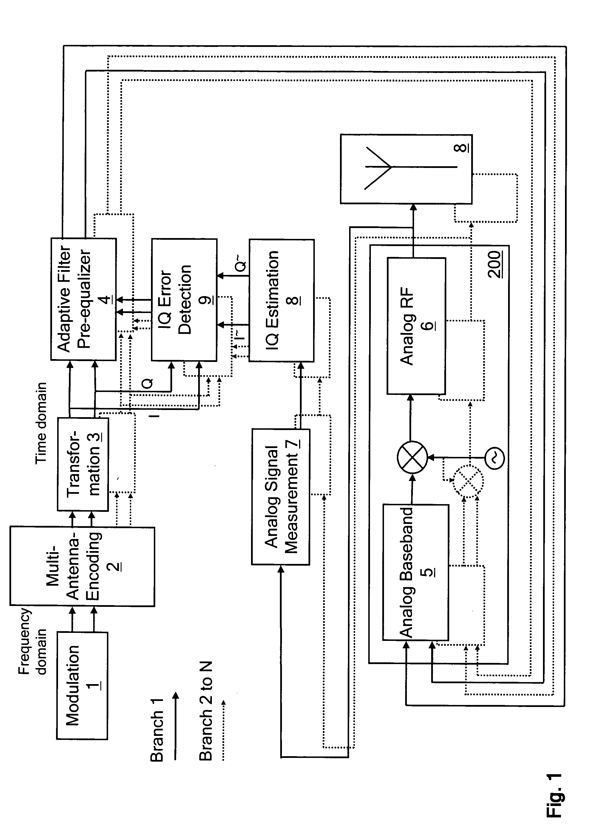
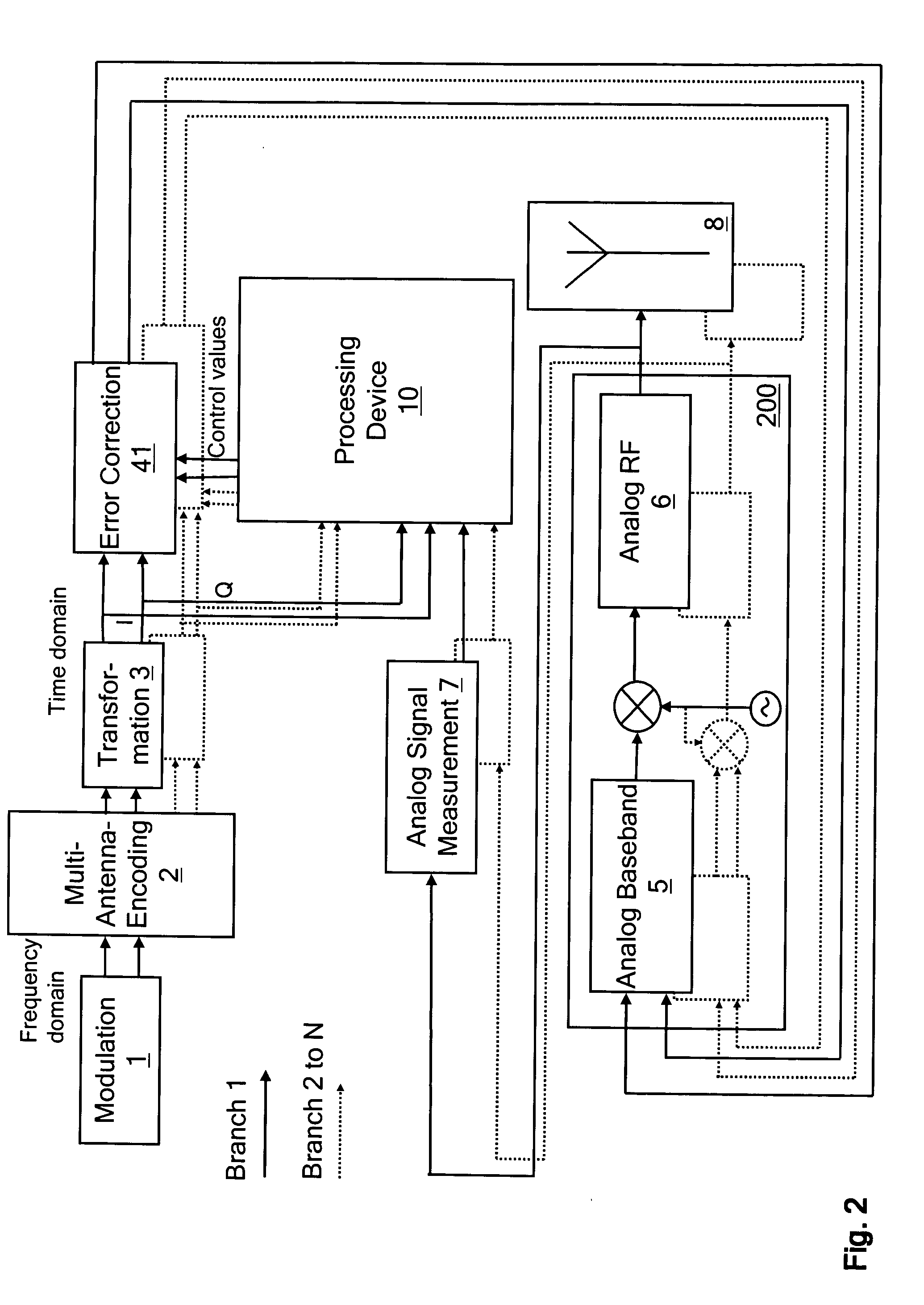
[0069] The embodiments of the invention can be applied in any data transmission system employing direct conversion architectures. Examples of such systems include Wireless LANs (Local Area Networks), Wireless MANs (Metropolitan Area Networks), digital radio DVB-T. A direct conversion architecture arranged, for example, in a transmitter, is an architecture where a base band frequency is converted directly to a radio frequency (RF) signal to be transmitted without any intermediate frequency (IF) conversion in between.

[0070] As an example of a system to which the embodiments of the invention may be applied, a Wireless Local Area Network (WLAN), Wireless Metropolitan Area Network (WMAN) is studied. WLAN, WMAN is a data transmission medium that uses radio waves in connecting computers to a network. The backbone network is usually wire line and the wireless connection is the last link of the connection between the LAN and users.

[0071] If the system requires high data-rates and a good sy...


PUM


Abstract

A processing device and method for an error adjustment system for equalizing transmission characteristics of N signal processing circuitries according to N signal branches (N>1) are disclosed. An original complex IQ signal of a signal branch of N signal branches and a processed real signal of the signal branch are received. A processed complex IQ signal of the signal branch is calculated from the processed real signal and the original complex IQ signal of the signal branch. Then, a difference between the processed complex IQ signal and the original complex IQ signal is calculated. Finally, control values of a correction function of the signal branch are calculated on the basis of the calculated difference. The calculated control values are supplied to the correction function of the signal branch. The receiving, calculating and supplying operations are performed for all N signal branches.

Description

FIELD OF THE INVENTION [0001] The present invention relates to error adjustment in direct conversion architectures. In particular, the invention relates to In-phase and Quadrature-phase based error adjustment using an envelope based In-phase and Quadrature-phase extraction in a multi-antenna transmitter. BACKGROUND OF THE INVENTION [0002] The use of digital wireless communication systems has recently been increasing. Systems of many different types have been introduced. For example, systems like Wireless LANs (Local Area Networks), Wireless MANs (Metropolitan Area Networks), digital radio DVB-T are gaining more attention and users are given more alternatives in wireless communication. To get customers interested in new services it is essential that the equipment needed in order to use the services should be priced correctly. Transceivers with low cost and low power consumption are thus needed. [0003] The Institute of Electrical and Electronics Engineers (IEEE) has developed new spec...

Claims


Application Information

Patent Timeline
Patent Type & Authority Applications(United States)
IPC IPC(8): H04L1/06H04L27/00H04L27/26H04L27/36
CPCH04L1/06H04L27/2626H04L2027/0018H04L27/368H04L2027/0016H04L27/364
Inventor COERSMEIER, EDMUND
Owner NOKIA SOLUTIONS & NETWORKS OY
Why Eureka
Try Eureka