Two stage catalytic combustor

Inactive Publication Date: 2005-09-15
SIEMENS ENERGY INC
View PDF36 Cites 17 Cited by
  • Summary
  • Abstract
  • Description
  • Claims
  • Application Information

AI Technical Summary

Problems solved by technology

), but higher combustion temperatures have proven to

Method used


Image

  • Two stage catalytic combustor
  • Two stage catalytic combustor
  • Two stage catalytic combustor

Examples


Embodiment Construction

[0017] The inventors have developed an innovative two-stage catalytic combustor for partially catalytically combusting a fuel / air mixture in a first-stage at a relatively lower temperature, and then catalytically completing combustion of the partially oxidized fuel / air mixture in a second-stage at a relatively higher temperature. Advantageously, the first-stage partial combustion elevates the temperature of the partially oxidized fuel / air mixture entering the second-stage to a temperature sufficient for activating a catalyst in the second-stage to completely combust the partially oxidized fuel / air mixture. Accordingly, by providing complete catalytic combustion, pollutant formation may be reduced compared to other conventional catalytic combustion techniques.

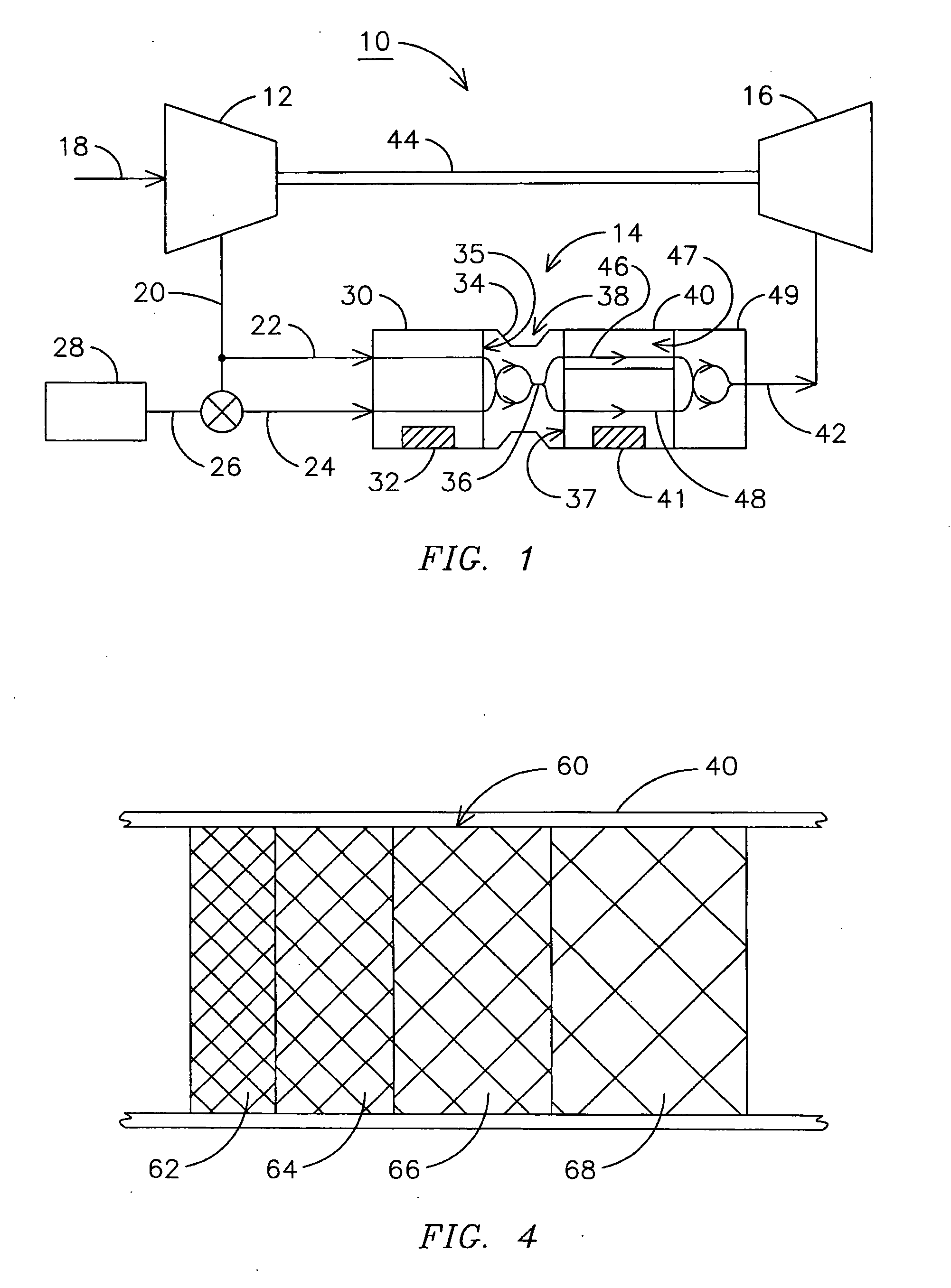
[0018]FIG. 1 is a functional diagram of a gas turbine 10 including a two-stage catalytic combustor 14. The gas turbine 10 includes a compressor 12 for receiving ambient air 18 and producing compressed air 20. The compressed air...


PUM

PropertyMeasurementUnit
Fractionaaaaaaaaaa
Fractionaaaaaaaaaa
Pore sizeaaaaaaaaaa

Abstract

A catalytic combustor (14) includes a first catalytic stage (30), a second catalytic stage (40), and an oxidation completion stage (49). The first catalytic stage receives an oxidizer (e.g., 20) and a fuel (26) and discharges a partially oxidized fuel/oxidizer mixture (36). The second catalytic stage receives the partially oxidized fuel/oxidizer mixture and further oxidizes the mixture. The second catalytic stage may include a passageway (47) for conducting a bypass portion (46) of the mixture past a catalyst (e.g., 41) disposed therein. The second catalytic stage may have an outlet temperature elevated sufficiently to complete oxidation of the mixture without using a separate ignition source. The oxidation completion stage is disposed downstream of the second catalytic stage and may recombine the bypass portion with a catalyst exposed portion (48) of the mixture and complete oxidation of the mixture. The second catalytic stage may also include a reticulated foam support (50), a honeycomb support, a tube support or a plate support.

Description

FIELD OF THE INVENTION [0001] This invention relates generally to the field of power generation, and more particularly, to catalytic combustors. BACKGROUND OF THE INVENTION [0002] Catalytic combustion systems are well known in gas turbine applications to reduce the creation of pollutants, such as NOx, in the combustion process. One catalytic combustion technique known as the rich catalytic, lean burn (RCL™) combustion process includes mixing fuel with a first portion of compressed air to form a rich fuel mixture. The rich fuel mixture is passed over a catalytic surface and partially oxidized, or combusted, by catalytic action. Activation of the catalytic surface is achieved when the temperature of the rich fuel mixture is elevated to a temperature at which the catalytic surface becomes active. Typically, compression raises the temperature of the air mixed with the fuel to form a rich fuel mixture having a temperature sufficiently high to activate the catalytic surface. After passing...

Claims


Application Information

Patent Timeline
IPC IPC(8): B01D53/34
CPCF23R3/40
Inventor ALVIN, MARY ANNBACHOVCHIN, DENNISSMELTZER, EUGENE E.LIPPERT, THOMAS E.BRUCK, GERALD J.
Owner SIEMENS ENERGY INC
Why Eureka
Try Eureka