Reaction apparatus for producing silicon

a technology of reaction apparatus and silicon, which is applied in the direction of indirect heat exchangers, lighting and heating apparatus, silicon compounds, etc., can solve the problems of reducing raw gas reactivity and the tendency to by-product formation, and achieves the reduction of raw gas reactivity, shortening the distance, and reducing the space

Active Publication Date: 2005-09-15
TOKUYAMA CORP
View PDF4 Cites 192 Cited by
  • Summary
  • Abstract
  • Description
  • Claims
  • Application Information

AI Technical Summary

Benefits of technology

[0007] The inventors have made extensive and intensive studies with a view toward resolving the above problems. As a result, it has been found that in the above apparatus, the above problems are caused by the configuration in cross-sectional view of the inside face of the tubular vessel. That is, when a scaleup of a reactor wherein the inside face of the tubular vessel has the shape of simple circle, regular polygon or the like in cross-sectional view is carried out, there would be a space highly apart from the heated inside face of the tubular vessel, thereby inviting problems such as decrease of raw gas reactivity and tendency toward by-product formation. Studies have been conducted on the basis of this finding. As a result, it has been found that all the above problems can be solved by a reaction vessel comprising a vertically extending wall and a space surrounded by the wall wherein the space of the reaction vessel is of slit form in cross-sectional view so as to reduce the space highly apart from the wall's surface facing the space, namely, shortening the distance between the wall's surface capable of silicon deposition and the space where raw gas therein hardly contact with the wall's surface. The present invention has been completed on the basis of this finding.

Problems solved by technology

As a result, it has been found that in the above apparatus, the above problems are caused by the configuration in cross-sectional view of the inside face of the tubular vessel.
That is, when a scaleup of a reactor wherein the inside face of the tubular vessel has the shape of simple circle, regular polygon or the like in cross-sectional view is carried out, there would be a space highly apart from the heated inside face of the tubular vessel, thereby inviting problems such as decrease of raw gas reactivity and tendency toward by-product formation.

Method used


Image

  • Reaction apparatus for producing silicon
  • Reaction apparatus for producing silicon
  • Reaction apparatus for producing silicon

Examples


example 1

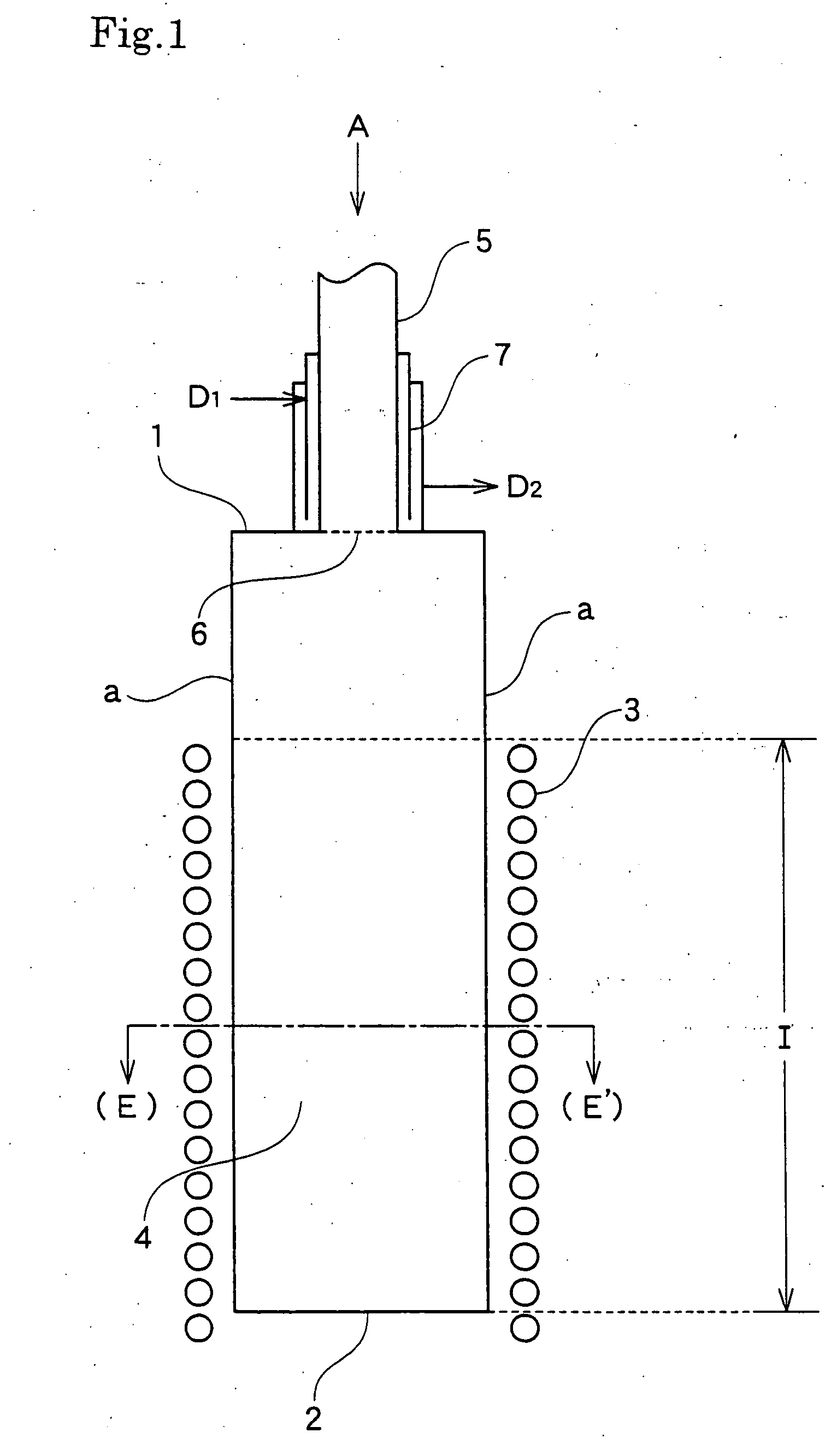
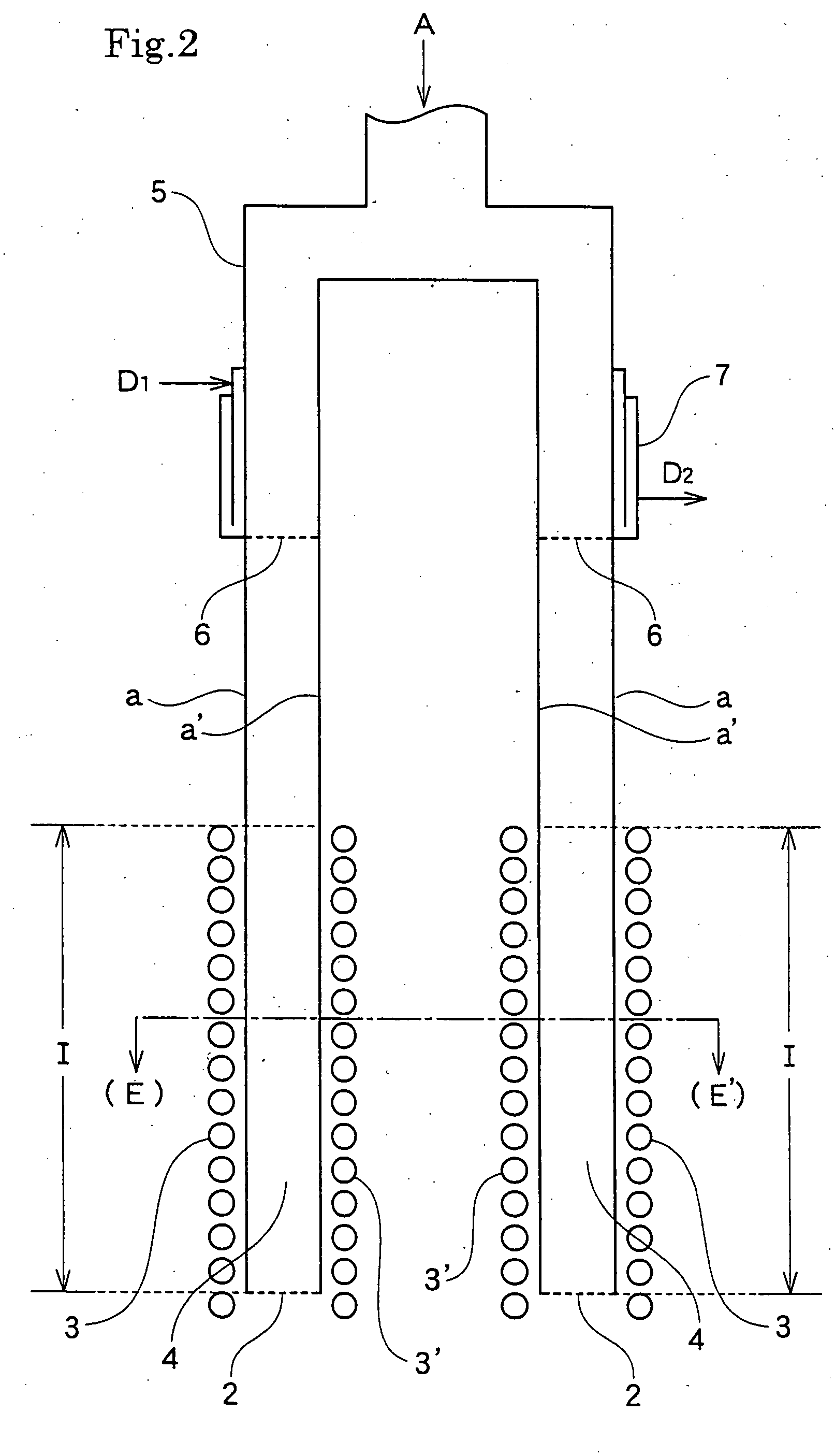
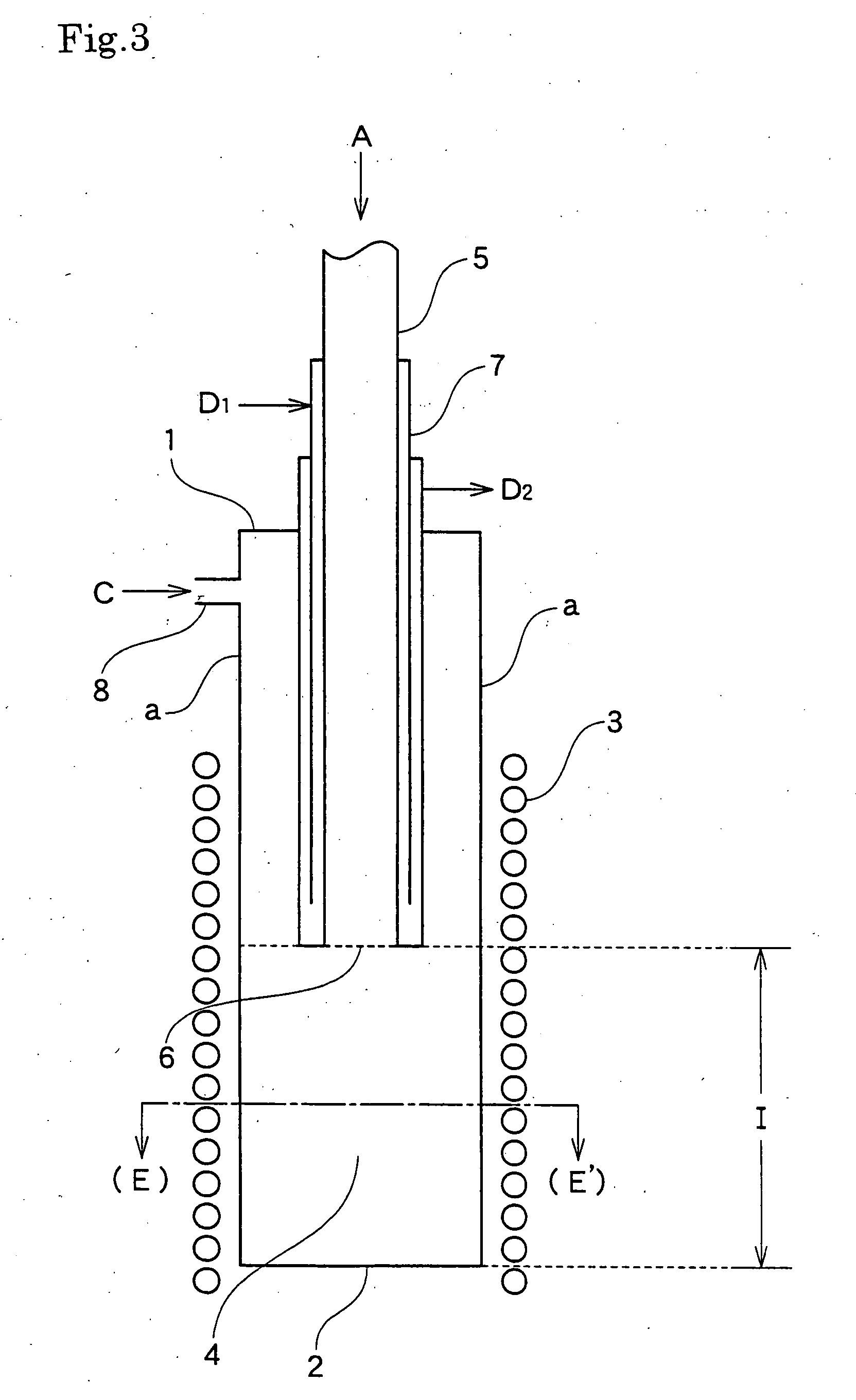
[0096] Use was made of reaction vessel (1) wherein the vertically extending wall (a) was constituted of graphite, the space (4) surrounded by the wall was of flattened form in cross-sectional view as shown in FIG. 8 and the vessel had the configuration of a cylindrical form of 0.1 m SD, 0.16 m LD, 15 mm thickness and 1.0 m length with opening (2) disposed at the bottom thereof. The raw gas supply pipe (5) was constituted of stainless steel, and the cooling means (7) had a jacket structure permitting liquid passage. The raw gas blowoff port (6) used was of 10 mm×100 mm slit form. The raw gas supply pipe (5) was disposed in the reaction vessel (1) so that the center and major diameter direction of the raw gas blowoff port (6) agreed with those of the flattened form of the space (4) and so that the height of the raw gas blowoff port (6) was such that the length of reaction zone (I) of FIG. 3 was 0.6 m. As the heating means (3) for heating the surface of wall (a) facing the space (4) in...

example 2

[0099] Reaction was performed under the same conditions with the use of the same reactor as in Example 1, except that the space (4) surrounded by the vertically extending wall (a) was changed to flattened form of 0.04 m SD and 0.2 m LD in cross-sectional view, that the raw gas blowoff port (6) of the raw gas supply pipe (5) was changed to 10 mm×170 mm slit form and that accordingly the configuration of high-frequency heating coil as the heating means (3) was changed so as to surround the reaction vessel (1) with a 50 mm thick heat insulating material interposed therebetween. The results are summarized in Table 1. The generation of fine powder silicon was extremely slight.

example 3

[0100] Reaction was performed under the same conditions with the use of the same reactor as in Example 2 except for the following. The space (4) surrounded by the vertically extending wall (a) was changed to flattened form of 0.04 m SD and 1 m LD in cross-sectional view. Accordingly, the configuration of high-frequency heating coil as the heating means (3) was appropriately changed. The raw gas blowoff port (6) was changed to 10 mm×970 mm slit form. With respect to the sealed vessel (10), the interior thereof was of flattened form in cross-sectional view as shown in FIG. 8, and the minor axis and major axis were changed to 0.5 m and 3 m, respectively. The direction of the flattened form was the same as that of the flattened form of the space (4).

[0101] Reaction was performed by effecting flow of hydrogen gas from the seal gas supply pipe (8) and seal gas supply pipe (11) simultaneously at a rate of 25 Nm3 / H and feeding trichlorosilane and hydrogen through the raw gas supply pipe (5...


PUM

PropertyMeasurementUnit
widthaaaaaaaaaa
temperaturesaaaaaaaaaa
widthaaaaaaaaaa

Abstract

A silicon production reactor comprising a reaction vessel and heating means, said reaction vessel comprising a vertically extending wall and a space surrounded by the wall, said heating means being capable of heating at least a part, including lower end portion, of the wall's surface facing the space to a temperature of not lower than the melting point of silicon, said silicon production reactor being adapted to flow raw gas for silicon deposition from an upper part of the space of the reaction vessel toward a lower part thereof, characterized in that the space of the reaction vessel is of slit form in cross-sectional view. This silicon production reactor is capable of attaining improvement with respect to problems encountered at apparatus scaleup, such as decrease of reactivity of raw gas and generation of by-products, thereby accomplishing a striking enhancement of production efficiency.

Description

TECHNICAL FIELD [0001] The present invention relates to a novel silicon production reactor. More particularly, the present invention relates to a silicon production reactor that in the industrial production of silicon continuously performed for a prolonged period of time, is capable of enhancing the reactivity of raw gas and capable of suppressing the generation of by-products to thereby maintain a high silicon yield and attain an enhancement of production efficiency. BACKGROUND ART [0002] In the art, various processes for producing silicon for use as a raw material for semiconductors and photocells are known. Some thereof are already put into industrial practice. [0003] For example, there can be mentioned the process known as Siemens process. In the Siemens process, a silicon rod having been heated to silicon deposition temperature by current passage is disposed in a bell jar, and trichlorosilane (SiHCl3, hereinafter referred to as TCS) or monosilane (SiH4) together with a reducing...

Claims


Application Information

Patent Timeline
Patent Type & Authority Applications(United States)
IPC IPC(8): C01B33/035H01L21/00
CPCC01B33/035Y10T117/1016Y10T117/10H01L21/67109
Inventor NAKAMURA, YASUOWAKAMATSU, SATORU
Owner TOKUYAMA CORP
Why Eureka
Try Eureka