Unlock instant, AI-driven research and patent intelligence for your innovation.

Method of configuring information processing system and semiconductor integrated circuit

a technology of information processing system and integrated circuit, which is applied in the direction of instruments, pulse techniques, computation using denominational number representation, etc., can solve the problems of poor area-utilizing efficiency of integrated circuit, large area and large volume of programmable logic, and the inability to freely shift and use circuits, etc., to achieve flexible handling, reduce circuit size, and reduce the manufacturing cost of programmable logic

Inactive Publication Date: 2005-09-15
PANASONIC CORP
View PDF0 Cites 0 Cited by
  • Summary
  • Abstract
  • Description
  • Claims
  • Application Information

AI Technical Summary

Benefits of technology

[0014] According to the foregoing constitution, the parameter representing invariability corresponding to the relevant process is judged as an inputted condition for each module constituting the application, and the module whose parameter representing invariability is high demanding no change thereafter is allocated to the exclusive-use circuit. In such a manner, a circuit area of a minimum size can be realized. On the contrary, the module in which the parameter is low and the necessity of the change is high is allocated to the programmable logic (microcomputer, DSP, re-configurable LSI or the like). Accordingly, the change can be flexibly handled through rewriting the program. As a result, a manufacturing cost of the programmable logic can be curtailed as a result of reducing the circuit size and an increased efficiency of the area utilization thereby achieved.

Problems solved by technology

However, the programmable logic generally consumes a larger area and a larger volume of power in comparison to any exclusive-use hardware.
In the case in which the sharable part on the circuits is small and there are many non-exclusive independent circuits, an area where the circuits can be freely shifted and used is quite limited.
Therefore, an area-utilizing efficiency of the integrated circuit is poor and the circuit size is thereby increased, which unfavorably increases the manufacturing cost of the programmable logic circuit.

Method used


Image

  • Method of configuring information processing system and semiconductor integrated circuit
  • Method of configuring information processing system and semiconductor integrated circuit
  • Method of configuring information processing system and semiconductor integrated circuit

Examples


embodiment 1

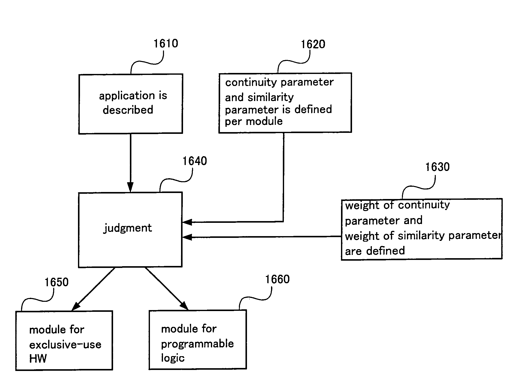
[0157] Hereinafter, a method of configuring an information processing system according to an embodiment 1 of the present invention is described referring to FIGS. 3 through 5.

[0158] In Step 310, a designer describes an application by means of a drawing or a language. For example, a high-level language such as C language or RTL (Register Transfer Level) is used to describe the application in a plurality of modules. FIG. 4 shows a demodulation process in CDMA (Code Division Multiple Access) communication as an example of the application.

[0159] A demodulation process 400 is comprised of five modules from a despreading 401 through an error correction 405, and the description is carried out in a language for each module. There is no limitation to a unit of the description.

[0160] In Step 320, a continuity parameter is inputted per module. The continuity parameter is an indicator which indicates if it is unnecessary to change a process at any time point in the future or if it is necessa...

embodiment 2

[0167] Hereinafter, a method of configuring an information processing system according to an embodiment 2 of the present invention is described referring to FIGS. 6 through 8.

[0168] In Step 610, the designer describes an application by means of a drawing or a language. For example, the description is carried out in the high-level language such as the C language and or RTL in a plurality of modules. As an example of the application, a demodulation process in wireless LAN (Local Area Network) communication is shown in FIG. 7.

[0169] A demodulation process 700 is comprised of seven modules from an automatic frequency control 701 to a Viterbi decoding 707, and the description is carried out for each module in a language. There is no limitation to a unit of the description.

[0170] In Step 620, a data-dependency parameter is inputted for each module. The data-dependency parameter is an indicator which indicates if a volume of data to be processed is constant or variable.

[0171] The data-...

embodiment 3

[0178] Hereinafter, a method of configuring an information processing system according to an embodiment 3 of the present invention is described referring to FIGS. 9 through 11.

[0179] In Step 910, the designer describes an application by means of a drawing or a language. For example, the description is carried out in a plurality of modules by means of the high-level language such as the C language or RTL. As an example of the application, a demodulation process (1000) in the CDMA communication is shown in FIG. 10A, and a demodulation process (1010) in the wireless LAN communication is shown in FIG. 10B. The demodulation process 1000 of the CDMA communication is comprised of five modules from a despreading 1001 to a Viterbi decoding 1005, and the demodulation process 1010 is comprised of seven modules from an automatic frequency control 1011 to a Viterbi decoding 1017, based on which the description is carried out in a language. There is no limitation to a unit of the description.

[0...


PUM


Abstract

A method of configuring an information processing system according to the present invention, in an information processing system for realizing one or a plurality of applications, comprises, a step of modeling all of the applications for each certain process level and inputting the models, a step of inputting parameters representing invariability for the inputted models, a step of using the models of the applications and the parameters representing invariability as inputted information and comparing the parameters representing invariability to a boundary condition, and a step of allocating one of the application models to programmable logic and another of the application models to an exclusive-use hardware based on a result of the comparison.

Description

BACKGROUND OF THE INVENTION [0001] 1. Field of the Invention [0002] The present invention relates to an information processing system for realizing an application using programmable logic capable of reconfiguring a semiconductor integrated circuit after the semiconductor integrated circuit is manufactured, more particularly to a method of configuring the information processing system including the programmable logic, and further, to a semiconductor integrated circuit to which the method of configuring the information processing system is applied. [0003] 2. Description of the Related Art [0004] In processing different kinds of digital signals, different kinds of semiconductor integrated circuits, examples of which are a microcomputer, DSP (Digital Signal Processor), ASIC (Application Specific Integrated Circuit), a memory element (memory) and the like, are used. In recent years, a programmable logic (such as microcomputer and DSP) capable of changing a process by means of a program a...

Claims


Application Information

Patent Timeline
Patent Type & Authority Applications(United States)
IPC IPC(8): G06F7/00G06F15/78G06F17/50H01L21/82H03K19/173
CPCG06F17/5054G06F30/34
Inventor OKABAYASHI, KAZUHIROOKAMOTO, MINORU
Owner PANASONIC CORP
Features
  • R&D
  • Intellectual Property
  • Life Sciences
  • Materials
  • Tech Scout
  • Unparalleled Data Quality
  • Higher Quality Content
  • 60% Fewer Hallucinations
Learn More