System for controlling the hydraulic actuated components of a truck

a technology for hydraulic actuation components and systems, applied in the direction of electric programme control, program control, instruments, etc., can solve the problems of raising the center of gravity of the truck, corrosive failure, and little improvement of highway traction

Inactive Publication Date: 2005-09-22
KIME JAMES A
View PDF3 Cites 40 Cited by
  • Summary
  • Abstract
  • Description
  • Claims
  • Application Information

AI Technical Summary

Benefits of technology

[0021] To further protect the electronic components within the composite housing from environmental attack, a pressurizing fille

Problems solved by technology

Thus, when into a given run, the dump bed will be elevated, dangerously raising the center of gravity of the truck under inclement driving conditions.
Many such sensors and feedback lines along with associated couplers are seasonally removed and even though of high quality, are prone to corrosive failure in view of the rigid environment the trucks are exposed to.
Without a disruption of that bond, little improvement to highway traction will be achieved.
For example, a plow merely will scrape off the snow and ice to the extent possible, only to leave a slippery coating which may be more dangerous to the motorist than the pre-plowed road conditions.
When salt has been simply broadcast over an ice laden pavement from a typical spinner, it will have failed to form a brine of sufficient salt concentration to break the ice-pavement bond.
The result is usually an ice coated pavement, in turn, coated with a highly dilute brine solution developed by too little salt, which will have melted an insufficient amount of ice for traction purposes.
In general, an adequate salt concentration using conventional dispersion methods requires the distribution of an unacceptable quantity of salt on the pavement.
A result has been that the thus-deposited brine concentration essentially immediately dilutes to ineffectiveness at the ice surface.
Attempting to remove ice from pavement by dissolving the entire amount present over the entire expanse of pavement to be treated is considered not to be acceptable from an economical as well as environmental standpoint.
The pro

Method used


Image

  • System for controlling the hydraulic actuated components of a truck
  • System for controlling the hydraulic actuated components of a truck
  • System for controlling the hydraulic actuated components of a truck

Examples


Embodiment Construction

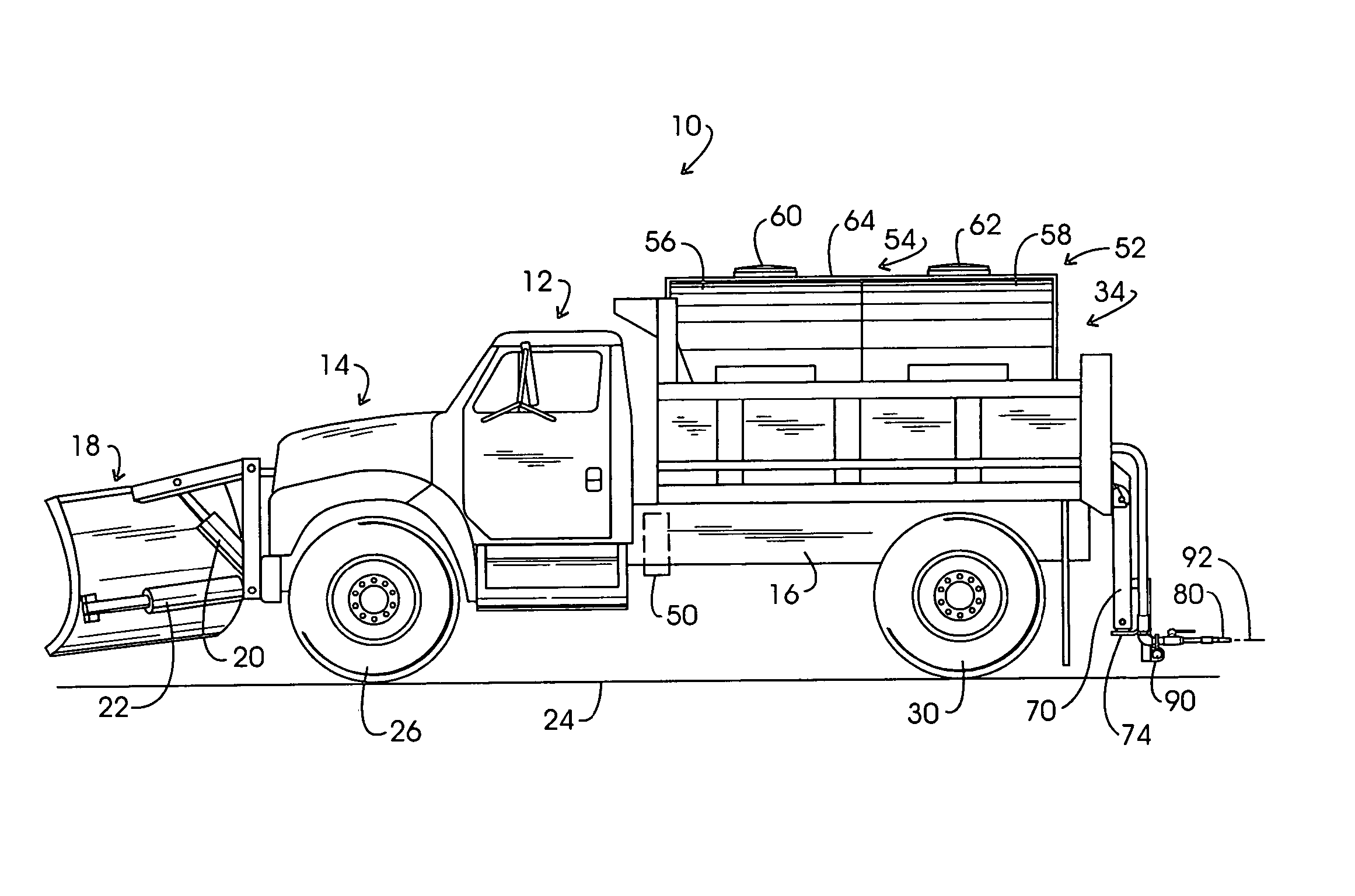
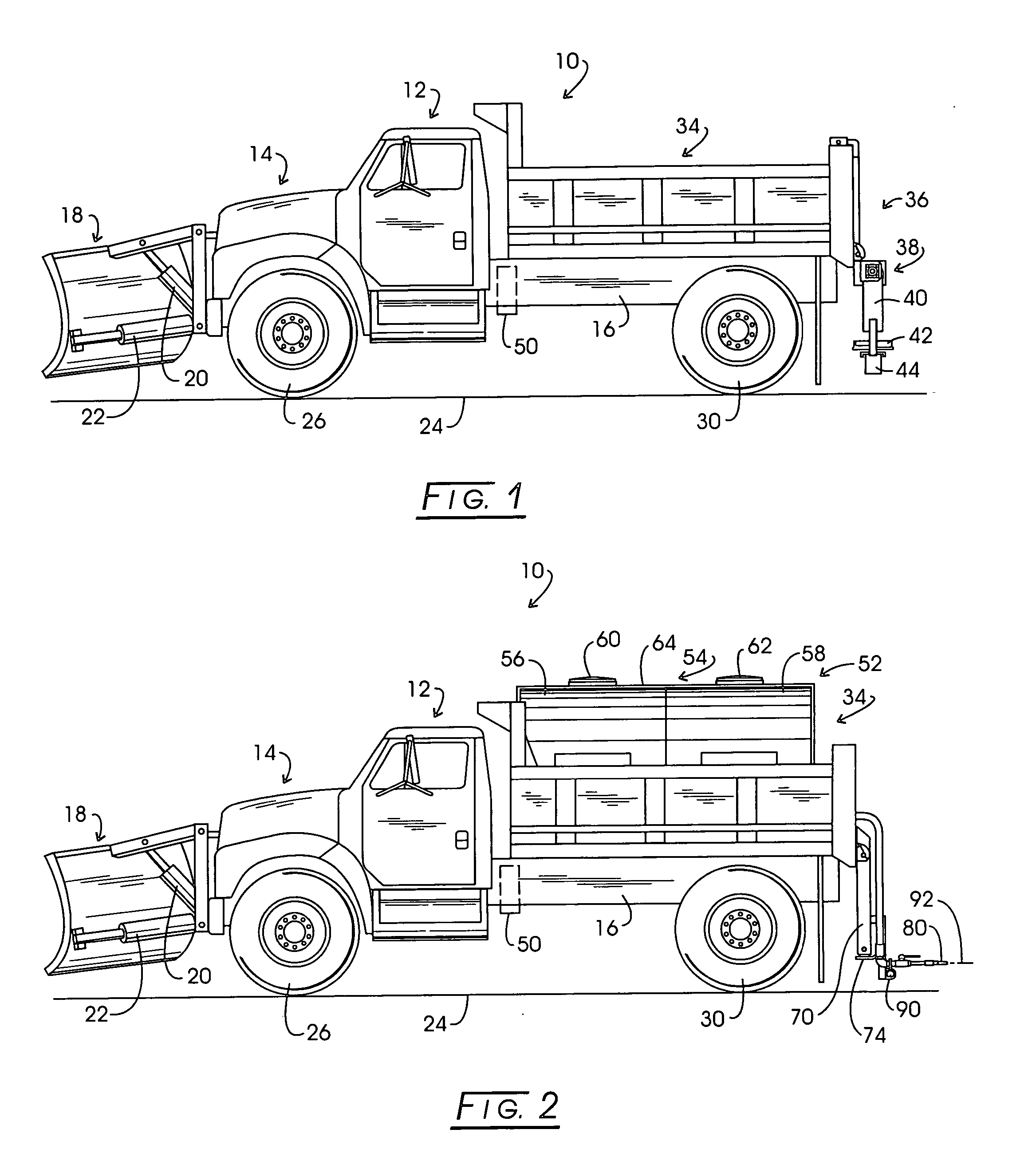
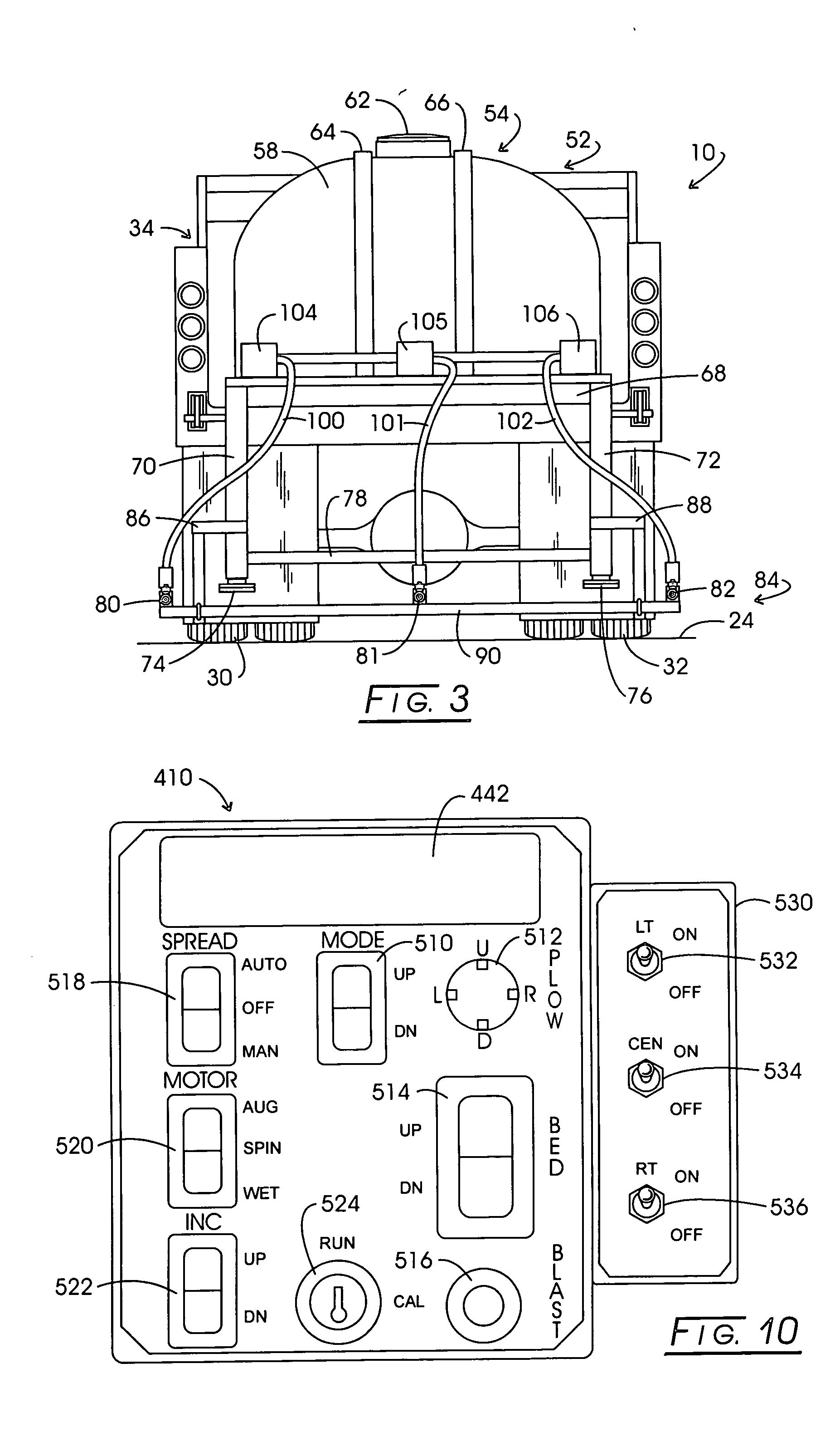
[0045] In the discourse to follow, the system and apparatus for controlling truck-mounted hydraulically actuated components is illustrated in connection with exemplary trucks having gross vehicle weights (GVW) less than 26,000 pounds. Because the system employs a truck frame-mounted hermetically secure reservoir and manifold composite of assembly incorporating its own control assembly and associated slave composite assembly controller, communication to the truck cab operator interface and an associated master controller is by the advantageous expedient of using a bidirectional data transmission bus. Thus the system is readily installed in trucks with cabs of widely varying layout. Software employed with the multi-controller system is designed to accommodate the more elaborate hydraulic circuits of larger, principal highway traveling snow-ice control configured trucks. The system may be employed to control any of a wide variety of truck snow-ice control configurations both for deposi...


PUM


Abstract

A system for controlling the hydraulically actuated components, including snow-ice control components carried by a truck. The system employs a hermetically secure composite housing mounted externally of the truck cab on the truck frame which retains a unique hydraulic reservoir in combination with a manifold supporting a plurality of solenoid actuated hydraulic valves and an associated electronic drive circuitry including a slave controller having a bidirectional data transmission port. That port communicates through a single bidirectional transmission bus with a master controller retained within an operator interface control console mounted in the truck cab. That control console also will contain a slave interface controller, as well as a slave datalog and communications controller.

Description

CROSS-REFERENCE TO RELATED APPLICATIONS STATEMENT REGARDING FEDERALLY SPONSORED RESEARCH [0001] Not applicable. BACKGROUND OF THE INVENTION [0002] Snow and ice control over primary, high speed highways such as interstate systems typically is carried out by governmental authorities with the use of dump trucks which are quite robust, for example, typically exceeding 28,000 pounds gross vehicle weight (GVW). This robust size requires operators with commercial drivers license qualifications. In general, the trucks are somewhat similar in general layout of the cab and the like from manufacturer to manufacturer in view of the anticipated primary highway related endeavors. These trucks are seasonally modified by the addition of snow-ice treatment components. Such components will include forwardly mounted plows, wing plows, scrapper plows and rearwardly-mounted mechanisms for broadcasting materials such as salt or brine containing salt. The classic configuration for the latter broadcasting ...

Claims


Application Information

Patent Timeline
IPC IPC(8): E01H5/06E01H10/00G06F12/00
CPCE01H10/007E01H5/06
Inventor KIME, JAMES A.
Owner KIME JAMES A
Why Eureka
Try Eureka