Tailpipe of automotive vehicle

a tailpipe and automotive technology, applied in the direction of machines/engines, mechanical equipment, gas passages, etc., can solve the problems of not being able to readily mount at the exhaust pipe, the backflow of exhaust into the engine, and noise serious, so as to reduce the length, reduce noise, and be easy to mount

Inactive Publication Date: 2005-09-22
LIN SHIN SENG
View PDF5 Cites 47 Cited by
  • Summary
  • Abstract
  • Description
  • Claims
  • Application Information

AI Technical Summary

Benefits of technology

[0005] It is an object of the present invention to provide a tailpipe of automotive vehicle. The tailpipe has a reduced length so as to be readily mounted at an exhaust pipe. The tailpipe comprises an outer ...

Problems solved by technology

This can build a back pressure in the chambers, resulting in a partial back flow of exhaust into the engine.
U.S. Pat. No. 4,792,014 discloses an excessively long tailpipe of internal combust...

Method used


Image

  • Tailpipe of automotive vehicle
  • Tailpipe of automotive vehicle
  • Tailpipe of automotive vehicle

Examples


Embodiment Construction

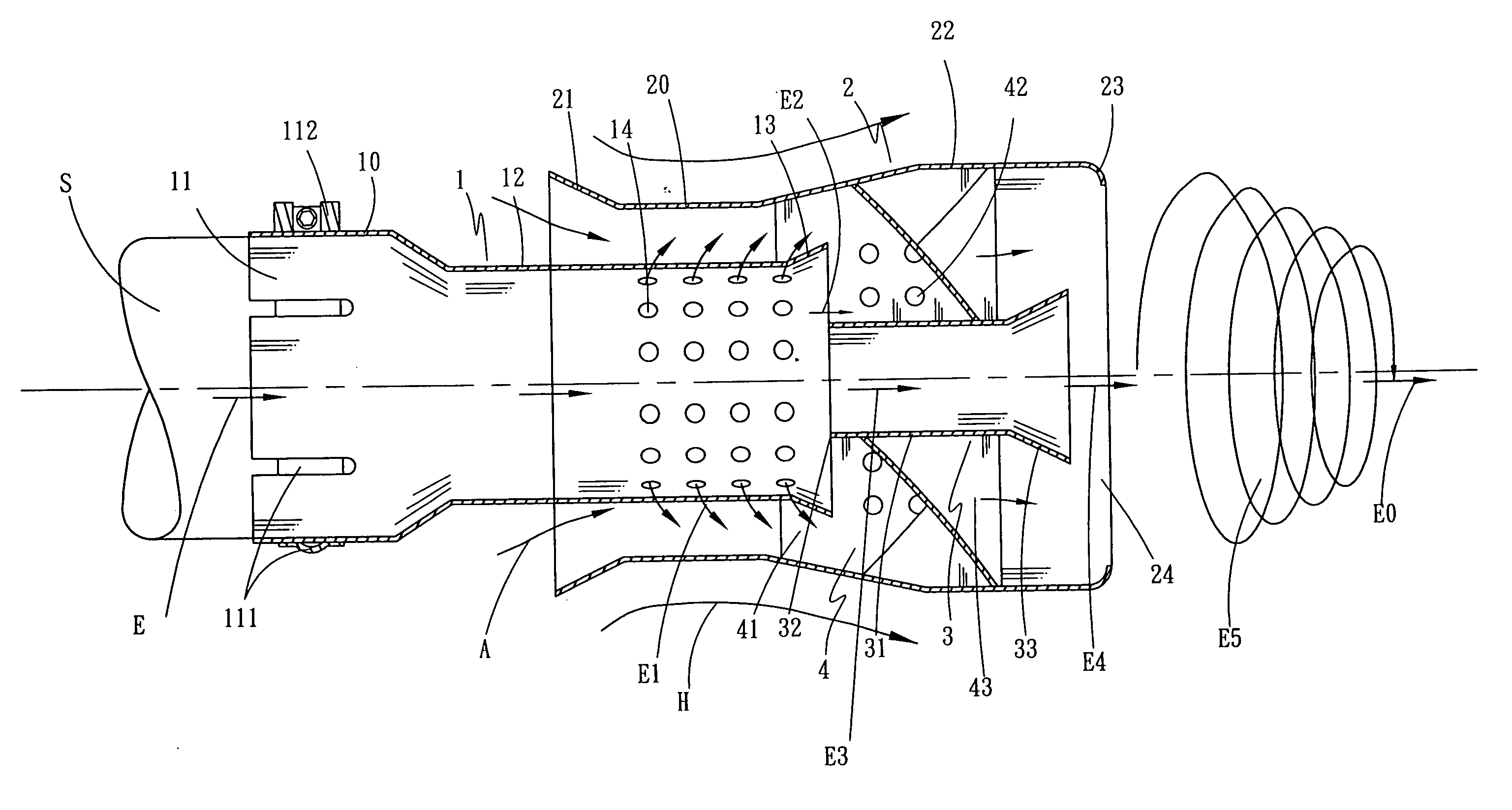
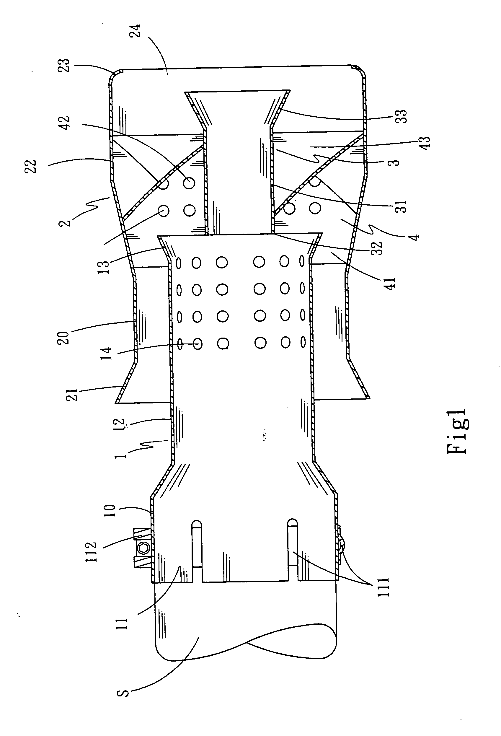
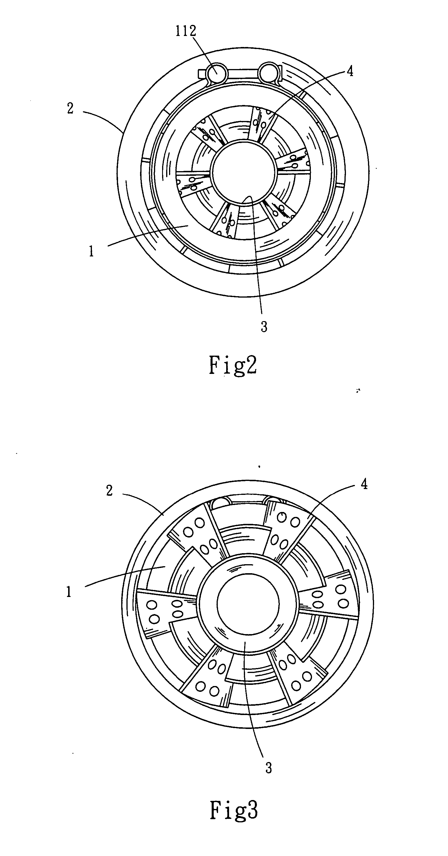
[0015] Referring to FIGS. 1 to 4, there is shown a tailpipe of an automotive vehicle constructed in accordance with the invention. The tailpipe comprises a front tube 1, an outer tube 2, a rear tube 3, and a plurality of twisted blades 4. Each component will be described in detail below.

[0016] The front tube 1 comprises a front section 10, a coupling 11 at the front section 10, the coupling 11 having a plurality of lengthwise slits 111 and a ring fastener 112 enclosed the coupling 11 for flexibly compressing the coupling 11 and fastening one end of a muffler S at the coupling 11, a flared rear section 13, and a neck 12 interconnected the front section 10 and the rear section 13, the neck 12 having a plurality of rows of apertures 14 on its surface.

[0017] The rear tube 3 comprises a front section 32 coupled to the rear section 13, an intermediate section 31 having a diameter slightly smaller than that of the front tube 1, and a flared rear section 33.

[0018] A rear portion of the f...


PUM


Abstract

A tailpipe of automotive vehicle comprises a front tube coupled to a muffler, the front tube including two flared ends and a neck having a plurality of apertures, a rear tube having a flared end, an outer venturi tube surrounded a rear portion of the front tube and the whole rear tube, the outer tube including a flared front end, a cylindrical section, an enlarged section, and a rear section having an inward extending rim at an opening thereof, and a plurality of twisted blades equally spaced apart around the rear tube and connected to the front, the rear, and the outer tubes, each blade having a plurality of apertures. Stream of exhaust from the muffler entering into the neck is divided into a number of components prior to forming whirlwind after leaving the tailpipe.

Description

BACKGROUND OF THE INVENTION [0001] 1. Field of the Invention [0002] The present invention relates to tailpipe of automotive vehicle and more particularly to such a tailpipe of automotive vehicle with improved characteristics. [0003] 2. Description of Related Art [0004] A conventional exhaust pipe of an internal combustion engine comprises an expansion chamber, a resonant chamber at the rear of the expansion chamber, and a plurality of perforated pipes disposed in both chambers, each pipe being enclosed by glass fibers or sound-absorbing material for silencing noise. Exhaust from the engine may flow into the chambers through apertures of the pipes. This can build a back pressure in the chambers, resulting in a partial back flow of exhaust into the engine. As an end, output torque of the engine is lowered due to incomplete combustion of the engine. U.S. Pat. No. 4,792,014 discloses an excessively long tailpipe of internal combustion engine such that it cannot be readily mounted at the...

Claims


Application Information

Patent Timeline
IPC IPC(8): F01N1/02F01N1/08F01N1/10F01N1/12F01N13/08
CPCF01N1/088F01N1/10F01N2470/30F01N2470/02F01N2470/20F01N13/082
Inventor LIN, SHIN-SENG
Owner LIN SHIN SENG
Why Eureka
Try Eureka