Habitat friendly, multiple impellor, wind energy extraction

a technology of wind energy and habitat, applied in the direction of wind energy generation, motors, sustainable buildings, etc., can solve the problems of difficult to obtain bird mortality statistics, visual and noise pollution, serious environmental hazards, etc., to save wildlife and people, clutter large tracts of rural land, and reduce vibration

Active Publication Date: 2005-09-22
TOCHER ANGUS J
View PDF27 Cites 21 Cited by
  • Summary
  • Abstract
  • Description
  • Claims
  • Application Information

AI Technical Summary

Benefits of technology

[0017] a downwind guidance for supporting a plurality of elements to include at least said one or more concentrator wings and said flow regulator, said downwind guidance presenting little obstruction to the higher speed wind flow upstream of said elements, said downwind guidance facilitating the orientation of said plurality of elements approximately into the oncoming wind and said downwind guidance comprising a lee support that supports said plurality of elements and extends in a downwind direction then turns outward and connects with a swivel that allows said plurality of elements to rotate around a common axis and effect said orientation;
[0030] 10. To provide a wind energy extraction system that may use multiple impellors and multiple power converters so that the task of preventing overspeeding of the impellors or power converters in higher wind conditions may be shared by the magnetic, electrical or mechanical resistance of the multiple power converters.

Problems solved by technology

In practice however, the use of popular wind turbines having rotor blades as long as 80 meters or longer and having tip speeds exceeding 100 mph introduce serious environmental hazards including visual and noise pollution and, perhaps of most immediate public concern, bird strikes.
Bird mortality is a fact that proponents of modern wind turbines do not like to advertise and it is difficult to obtain bird mortality statistics.
Rotor blade driven wind turbines pose a particular hazard to raptors, or birds of prey, many species of which are classified as endangered.
The hazard is amplified by the fact that wind farm sites are generally chosen or maintained clear of trees and bushes, and are often populated by small rodents or rabbits, prey of raptors or hunting birds.
The observed behavior of these birds is to focus so intently on the object of prey that they do not bercome aware of the hazard and are often struck and killed by the high speed rotor blades.
It is not practical or cost effective to attempt to fence out or otherwise exclude prey of these birds from wind farm sites.
This in turn causes a large proportion of the wind simply to divert around the turbine to rejoin well downstream or downwind of the device.
Aesthetics are important and in fact a distinct public criticism of wind farms in general is the visual marring of the natural landscape.
All of these devices add significant costs and many add considerable weight to the high speed rotor blades.
Adding aerodynamic wing tip brakes and associated hardware to precisely toleranced and balanced rotor blades increases design, manufacturing and maintenance costs.
As well, the added weight increases the demands made on the braking system itself and adds to the hazard should a component failure occur.
The powerful stream of air that is drawn by suction through the smallest diameter shrouds forces directly downstream and interferes with the flow of wind over and between the concentrator wings that is attempting to flow the wind outwards, away from the central axis.
These are contrary forces, and in higher wind conditions, as the article indicates, the stronger force wins with the resultant formation of a large turbulent vortex, the aerodynamic stalling of the concentrator wings, and the loss of power.
In so doing, it is unnecessary to optimize the impellor blades, certainly a futile attempt at least for higher speed winds.

Method used


Image

  • Habitat friendly, multiple impellor, wind energy extraction
  • Habitat friendly, multiple impellor, wind energy extraction
  • Habitat friendly, multiple impellor, wind energy extraction

Examples


Embodiment Construction

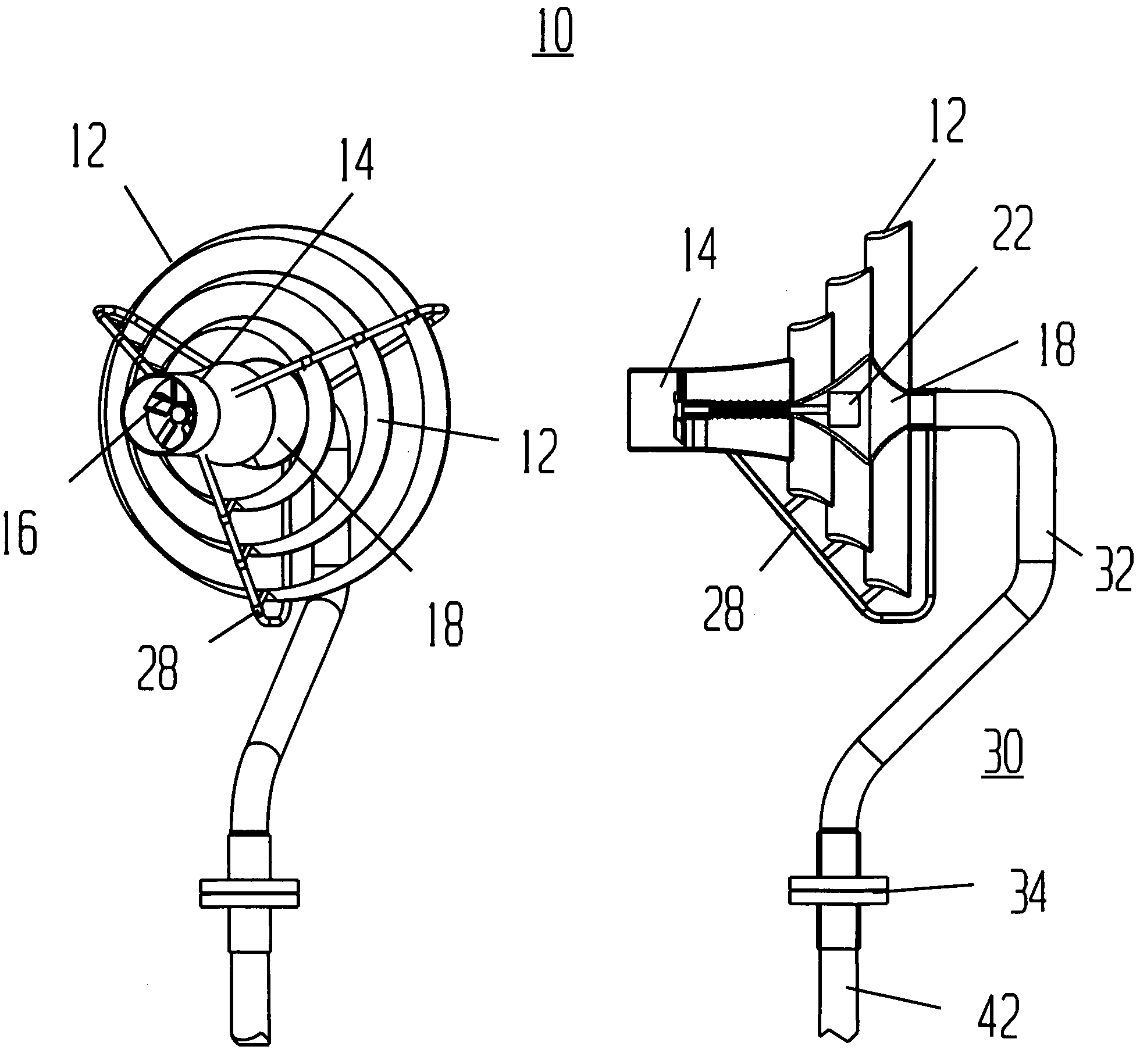
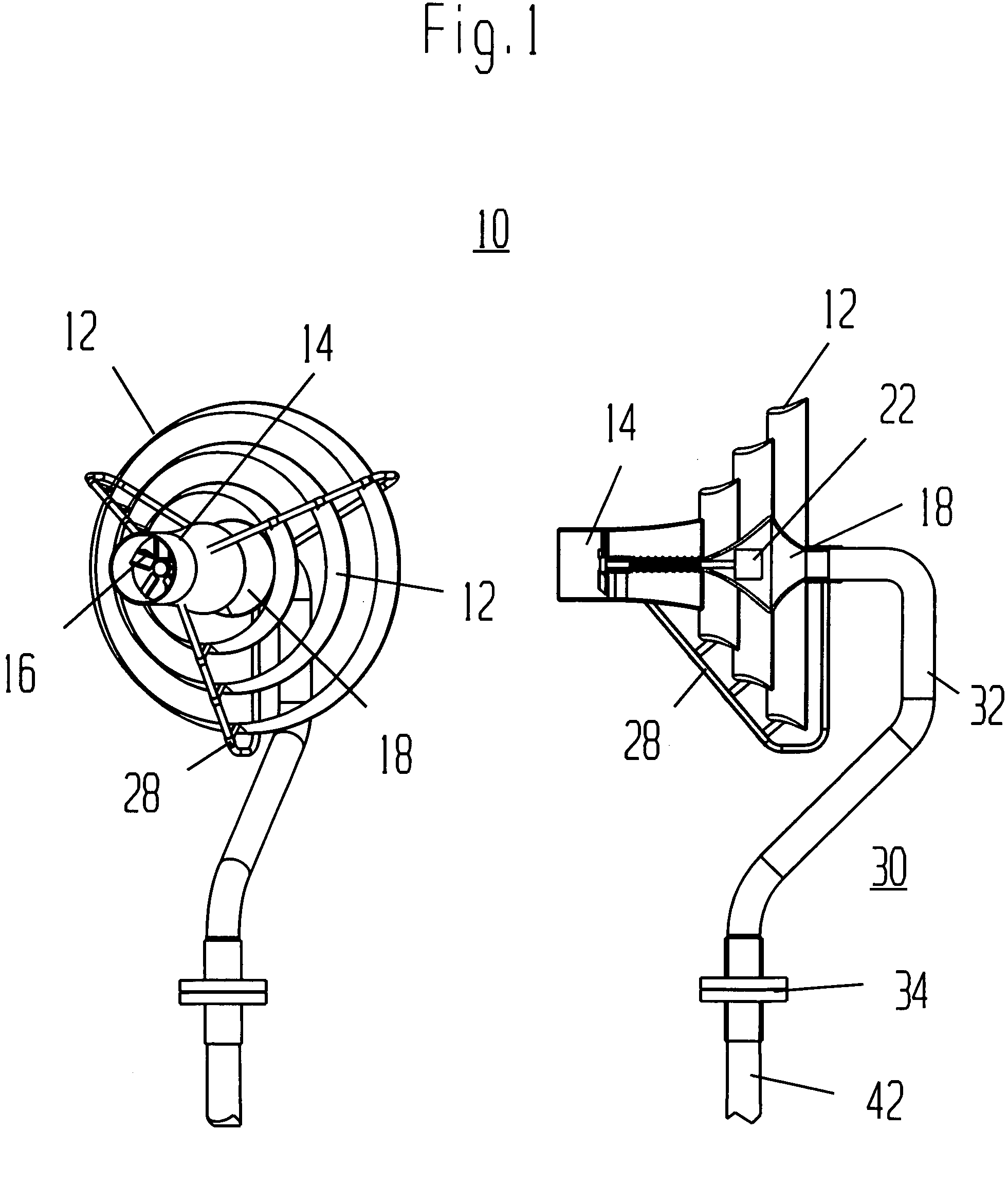
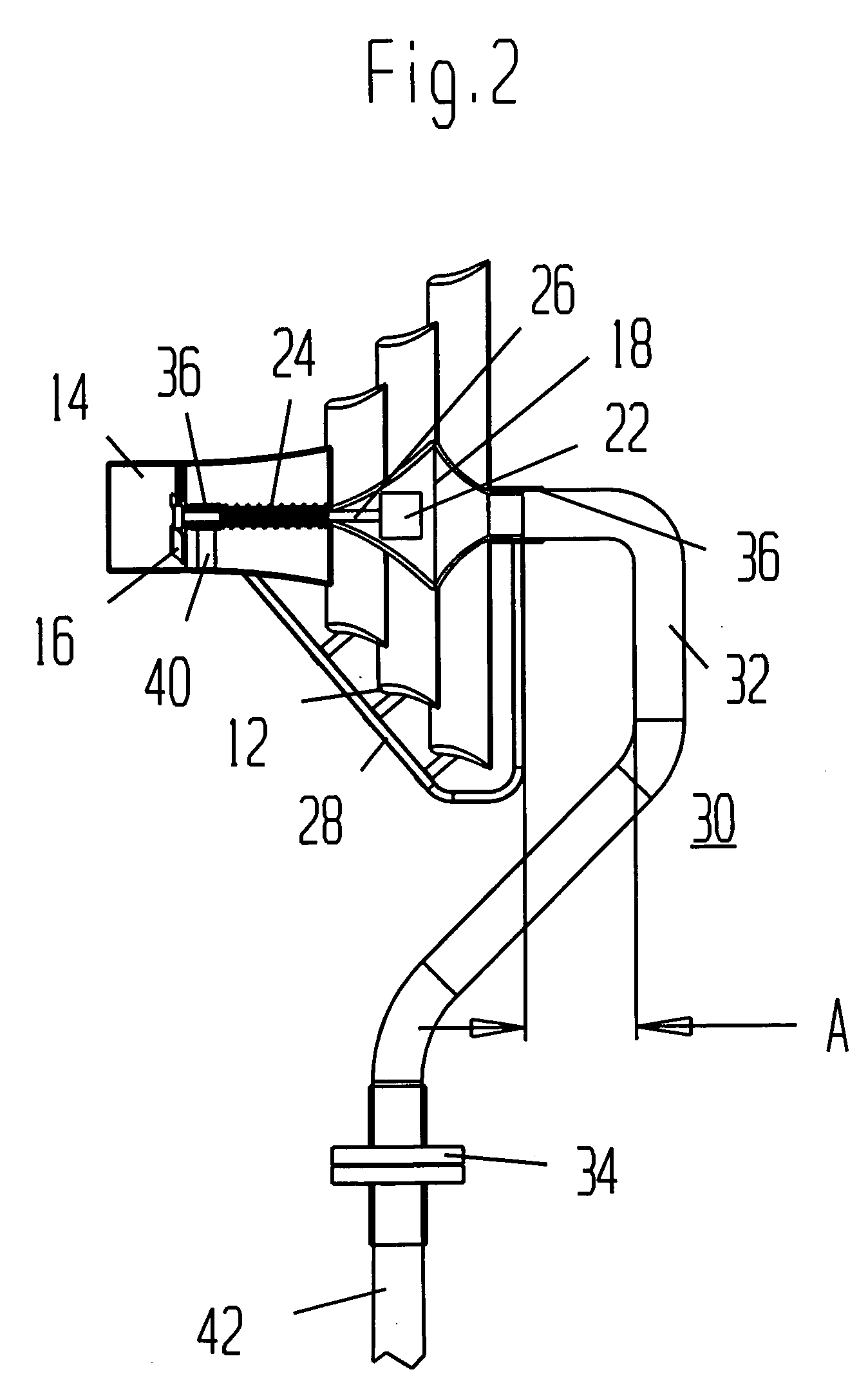
[0041] The description of invention 10 as presented in FIG. 1 must begin with a description of how shrouded wind turbines having one or more concentrator wings 12 operate. FIG. 6 therefore illustrates schematically, a cross section of the flow of wind through turbine shroud 14 and through three additional shrouds or concentrator wings 12. Turbine shroud 14 serves to enclose impellor 16 which in turn serves to react with the wind flowing through turbine shroud 14 and drive power converter 22, not shown in this illustration, such as an alternator or generator. Concentrator wings 12 operate fundamentally the same as aircraft wings and have similar profiles as may be readily seen from FIG. 6. These profiles generally have a top convex shaped surface to accelerate the flow of wind, and a lower flattened or concaved surface that tends to slightly decelerate the flow of wind past these surfaces. The profiles of concentrator wings 12 as illustrated are inclined, or have, in aeronautical ter...


PUM


Abstract

A habitat friendly, pressure conversion, wind energy extraction system is disclosed for safely extracting usable energy from wind. The invention includes one or more shrouds or concentrator wings that convert the dynamic pressure of wind into relatively lower static pressure and thereby induces a vacuum that draws wind into a turbine centralized within the shrouds or concentrator wings. As such, the turbine impellor blades may be significantly smaller than the large diameter rotor blades of current popular designs and may be enclosed within the shrouds or concentrator wings that present themselves as highly visible objects and as such are easily avoided by birds in flight. The invention in particular includes a device and method of airflow regulation than minimizes or prevents the stalling, or the generation of a turbulent flow of wind over or between the shrouds or concentrator wings of the invention. This stalling has been shown to occur when airflow is quickly accelerated by force of vacuum and drawn out of the turbine shroud which then mixes with and disturbs the otherwise smooth flow of wind over or between the shrouds or concentrator wings. The system may also include an aerobrake that responds quickly to protect the impellor blades or associated mechanisms from overspeeding or exceeding other design limitations under gusting or violent wind conditions. The invention may also include several other novel features such as power converters for extending the impellor or impellors into the free flowing accelerated wind, an aerobrake to protect the impellor from overspeeding, and two novel forms of into-wind guidance systems. Other advantages and objects are as well disclosed that increase safety and wind energy extraction efficiency and allow the invention to be effectively installed within urban settings.

Description

CROSS-REFERENCE TO RELATED APPLICATION [0001] This application is a continuation-in-part of U.S. patent application Ser. No. 10 / 802,291 filed Mar. 16, 2004 entitled “Habitat Friendly, Pressure Conversion, Wind Energy Extraction.” The entire disclosure of this prior application is considered to be part of the disclosure of this accompanying application and is hereby incorporated by reference.FIELD OF THE INVENTION [0002] The present invention relates to using wind energy and in particular, to safely and efficiently extracting energy from the wind and converting it to usable energy. BACKGROUND OF THE INVENTION [0003] The demand for alternative or renewable energy sources has dramatically increased during the last decade of the 20th century and continues in the new millennium. This demand is driven by the awareness of the depletion of the earth's non-renewable carbon based sources of energy of oil, gas and coal, and by the apparent effects of carbon waste emissions in particular, carbo...

Claims


Application Information

Patent Timeline
Patent Type & Authority Applications(United States)
IPC IPC(8): F03D1/04F03D7/00F03D7/04
CPCF03D1/04Y10S416/06Y02E10/72F05B2240/40F03D1/02F03D9/43Y02B10/30Y02E10/728
Inventor TOCHER, ANGUS J.
Owner TOCHER ANGUS J
Why Eureka
Try Eureka