Opposing pump/motors

a technology of opposing pumps and motors, which is applied in the direction of piston pumps, hybrid vehicles, gearing, etc., can solve the problems of reducing the life of the bearings, adding to the weight and cost of such systems, and achieving the effect of reducing the size of the bearings, reducing the weight and cost of the system, and increasing the efficiency of the system

Inactive Publication Date: 2005-09-22
THE UNITED STATES OF AMERICA AS REPRESENTED BY THE ADMINISTATOR OF THE U S ENVIRONMENTAL PROTECTION AGENCY EPA
View PDF99 Cites 15 Cited by
  • Summary
  • Abstract
  • Description
  • Claims
  • Application Information

AI Technical Summary

Benefits of technology

[0010] Any small residual axial loads are handled via bearings positioned on the shaft adjacent the drive plate assemblies in such a manner that the drive plate assemblies are in light axial contact only with the bearings. While this may be achieved in a variety of ways, in one embodiment, an annular bearing is located at a predetermined position that is spaced longitudinally from the pump / motor drive plate to form a small gap, the gap being filled by a spacer such as a shim, washer or spring. Given that the pump / motor drive plates are in rigid contact with each other through the common shaft, and are only in secondary, light contact with annular bearings, the vast majority of the axial load generated by each pump / motor is cancelled directly through the common shaft by the axial load of the opposing pump / motor, and only residual axial forces are transmitted to the bearings. As a result, as much as 90% or more of the friction experienced by the bearings in conventional systems is eliminated, and the size of the bearings may be reduced significantly as compared to prior art systems, thereby reducing the weight and cost of the system while increasing its efficiency.
[0011] To further reduce the loads on the bearings and increase the efficiency of the system, in one embodiment, the pump / motors are arranged to reduce the radial load carried by the bearings. More particularly, a device is coupled to an intermediate region of the shaft between the two annular bearings to transfer torque from the common input / output shaft to and from a secondary shaft. While this torque transferring device may be any known suitable device, in one embodiment, it is a plurality of gears. As will be understood by one of ordinary skill in the art, when two gears are coupled to transmit torque, they tend to want to separate, thereby generating a separation force in proportion to the torque. In accordance with the present invention, the first and second pump / motors are oriented to ensure that when the pump / motors stroke, they each generate a radial force in a direction that is opposite to that of the separation force generated by the torque transferring device, while being in the same plane as the separation force. By stroking the pump / motors in the same plane but in an opposite direction of the separation force, the radial forces on the bearing are reduced, thereby further reducing friction in the system.

Problems solved by technology

As each pump / motor may generate up to and beyond 10,000 pounds of axial force at its lowest displacement, the bearings experience high loads and friction, reducing the efficiency of the system and life of the bearings.
The bearings must therefore be sufficiently large to withstand these loads, adding to the weight and cost of such systems.

Method used


Image

  • Opposing pump/motors
  • Opposing pump/motors
  • Opposing pump/motors

Examples


Embodiment Construction

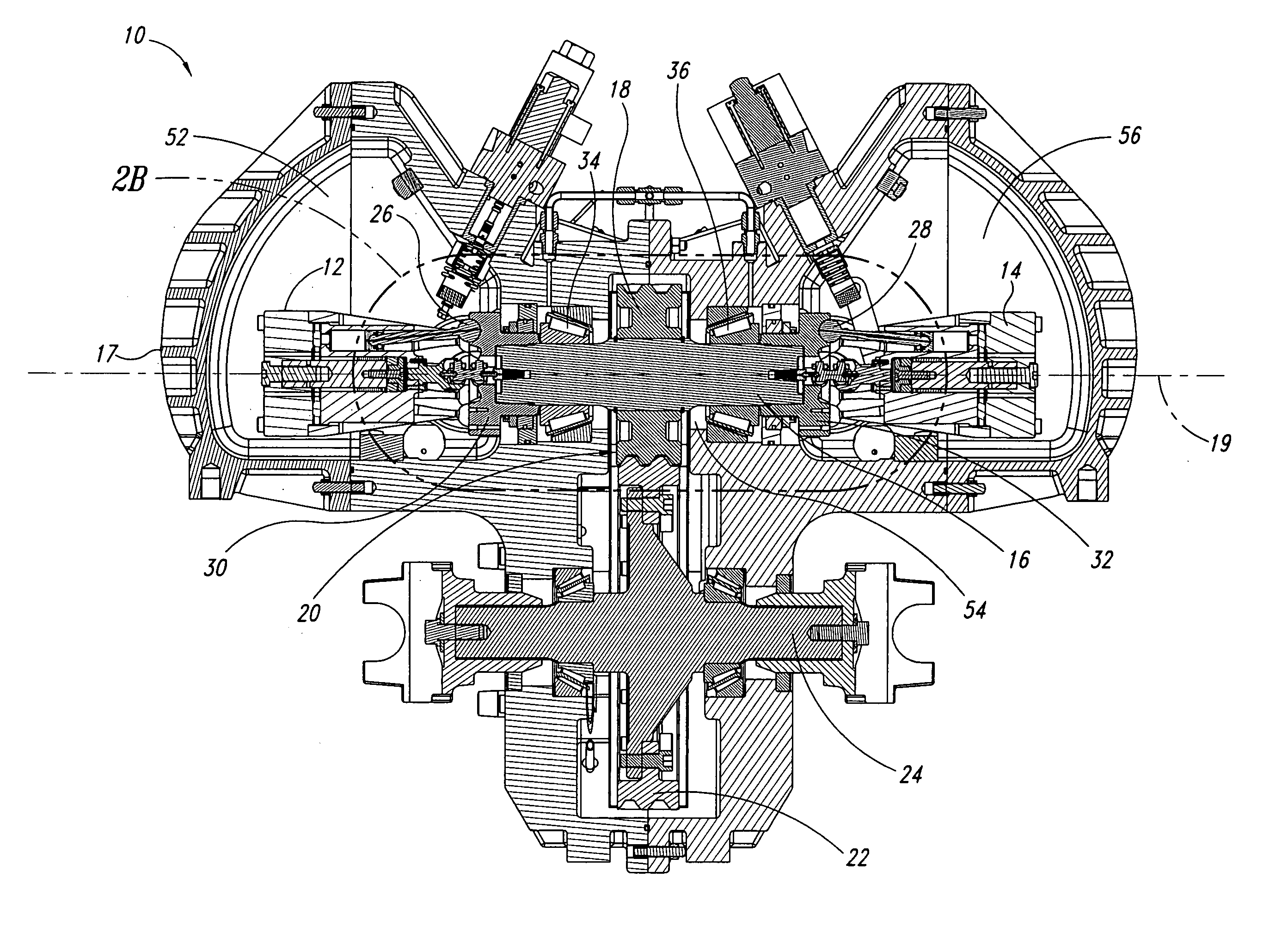
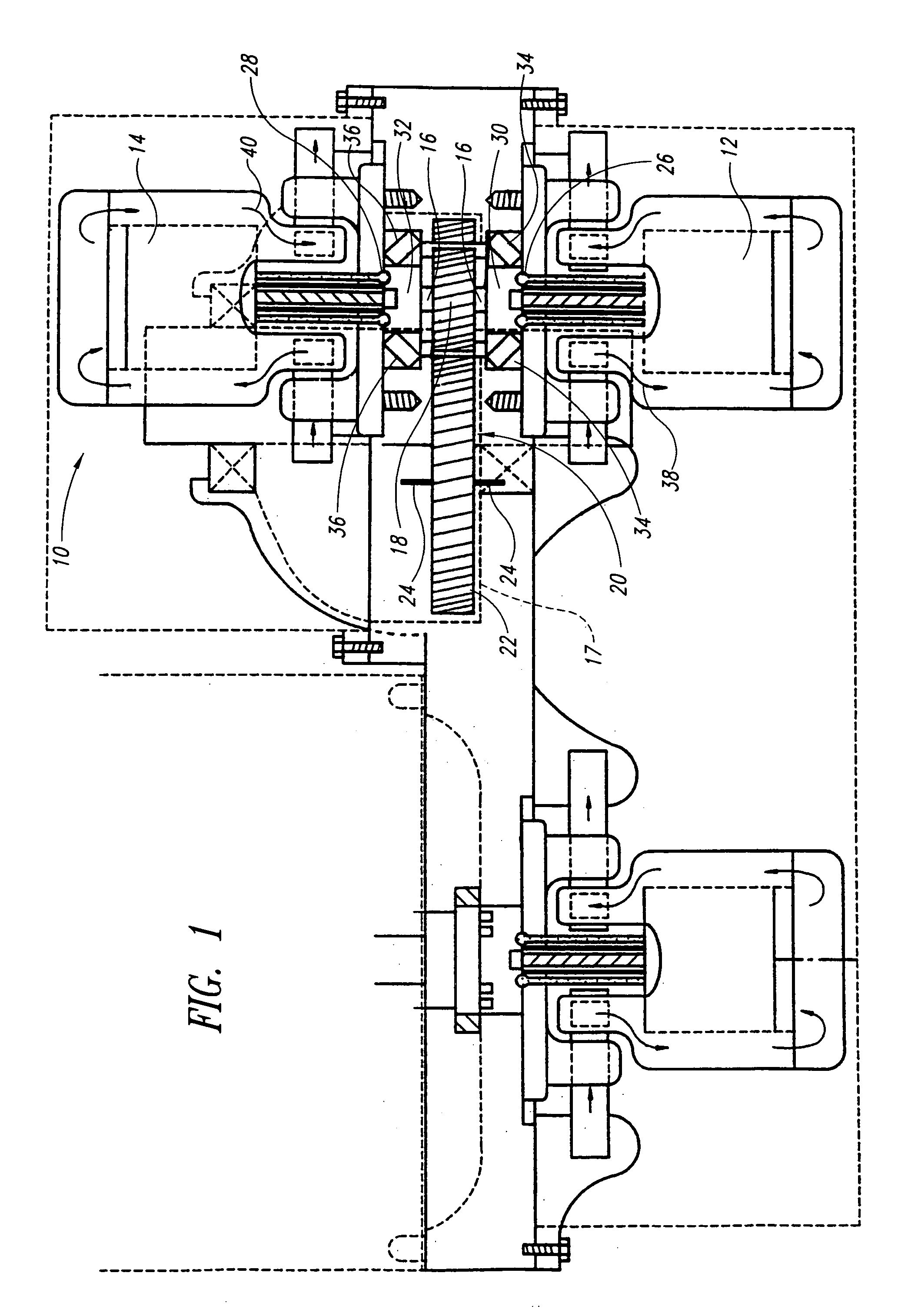
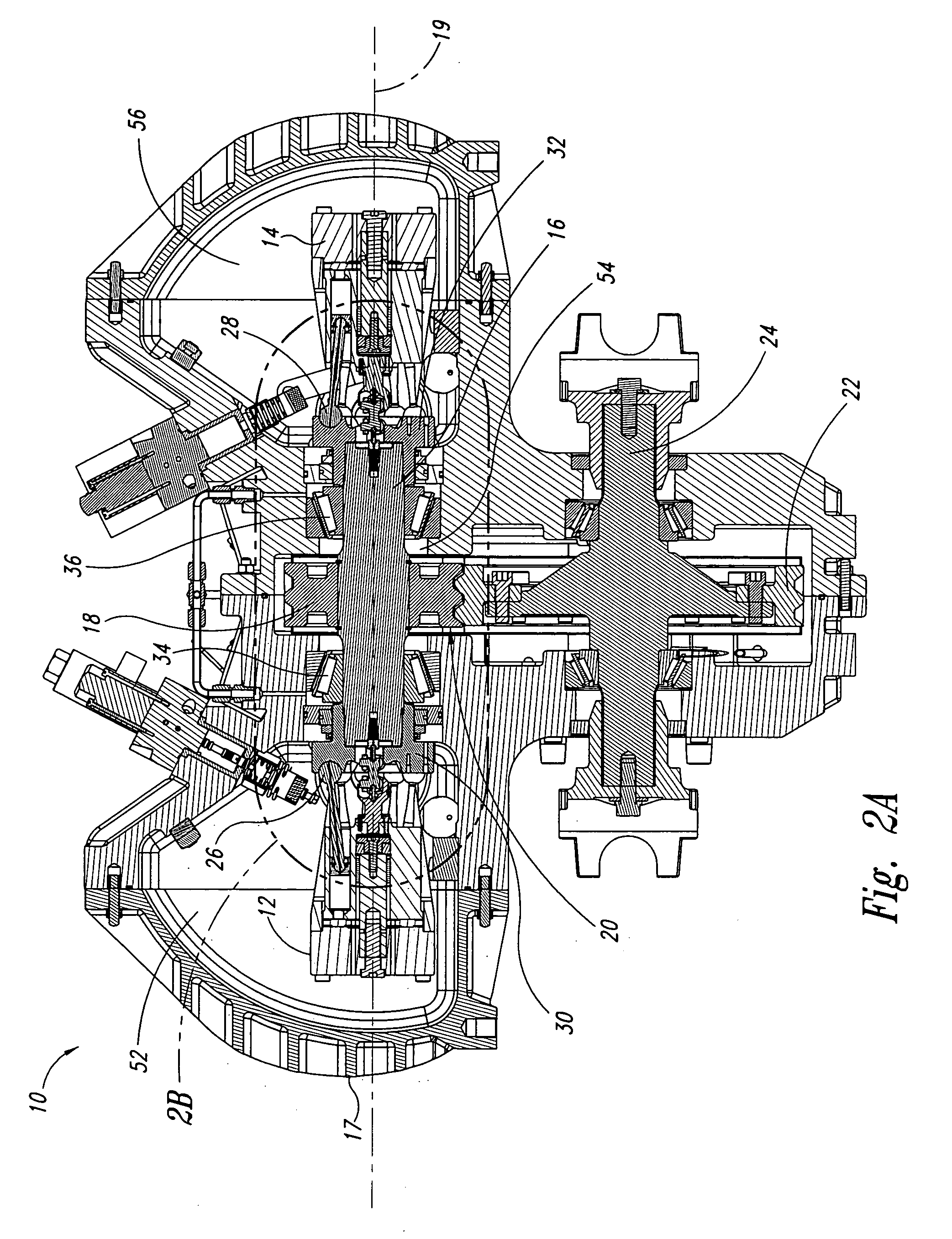
[0025] In the following description, certain specific details are set forth in order to provide a thorough understanding of various embodiments of the present invention. However, one of ordinary skill in the art will understand that the present invention may be practiced without these details. In other instances, well-known structures associated with pump / motors, and in particular, bent-axis piston machines, have not been shown or described in detail to avoid unnecessarily obscuring descriptions of the embodiments shown. Although the embodiments of the present invention are described herein, for ease of discussion, as having either a primarily horizontal or primarily vertical orientation, it should be understood that the embodiments of the present invention may be operated at a number of different angles.

[0026] Further, while certain embodiments of the present invention are described herein and in U.S. patent application Ser. No. 09 / 479,844 (the “Parent Application”) in the context...


PUM


Abstract

Two motors are arranged on opposing sides of a common shaft, drive plates of the pump/motors being rigidly coupled to each other, for example by being in hard contact with opposing sides of the shaft. By providing hard contact between the pump/motor drive plates and a common shaft, the drive plates and shaft act as a substantially solid element under compression, thereby substantially canceling axial loads generated by the pump/motors directly through the shaft. Residual axial loads are handled via bearings positioned on the shaft adjacent the drive plates in such a manner that the drive plates are in light contact only with the bearings. As a result, friction experienced by the bearings is substantially reduced as compared to conventional systems, thereby improving the efficiency of the system. To further reduce loads on the bearings, the pump/motors are arranged to ensure that they generate radial forces in a direction that is opposite to that of a separation force generated by a torque transferring device carried on the shaft and transmitted to the bearings. A common housing surrounding the two pump/motors, bearings and torque transferring device is divided into three regions, to segregate the bearings and torque transferring assembly from the pump/motors. In this manner, the regions containing the pump/motors are substantially filled with oil to, for example, fully lubricate the pump/motors, while the central region containing the gears and torque transferring device contains a significantly smaller volume of oil to simply splash lubricate the contents of the region, thereby reducing drag on the bearings. Control means are provided for selectively moving the two pump/motors substantially simultaneously to a selected displacement angle, using mechanical systems alone and in combination with hydraulic systems.

Description

CROSS-REFERENCE TO RELATED APPLICATIONS [0001] This application is a divisional of U.S. patent application Ser. No. 10 / 620,726, filed Jul. 15, 2003, now pending. U.S. patent application Ser. No. 10 / 620,726 is a continuation-in-part of U.S. patent application Ser. No. 09 / 479,844, filed Jan. 10, 2000, now U.S. Pat. No. 6,719,080, issued Apr. 13, 2004. These applications are incorporated herein by reference in their entireties.BACKGROUND OF THE INVENTION [0002] 1. Field of the Invention [0003] The present invention relates to hydraulic pump / motors uniquely arranged on a common shaft, including an apparatus for simultaneously changing the displacement of more than one pump / motor. [0004] 2. Description of the Related Art [0005] Hydraulic pump / motors such as bent-axis piston machines, are used for a variety of applications in numerous industries, including the marine, automotive and aerospace industries. Such pump / motors are commercially available from a number of manufacturers, for examp...

Claims


Application Information

Patent Timeline
Patent Type & Authority Applications(United States)
IPC IPC(8): B60K6/12B60K26/02B60K17/10F04B1/22F04B1/24F04B1/32F04B23/06F16H61/4096F16H61/44F16H61/448F16H61/452
CPCB60K6/12Y02T10/6208B60K26/02B60K41/162B60K2741/165B60W2540/10F04B1/22F04B1/24F04B1/328F04B23/06F16H61/4096F16H61/44F16H61/448F16H61/452F16H2039/005F16H2200/0034B60K17/10B60W10/04B60W10/10B60W30/18B60W2710/1005B60W2710/105Y02T10/62B60K2006/126
Inventor GRAY, CHARLES L. JR.
Owner THE UNITED STATES OF AMERICA AS REPRESENTED BY THE ADMINISTATOR OF THE U S ENVIRONMENTAL PROTECTION AGENCY EPA
Why Eureka
Try Eureka