Secondary battery of assemble-type structure

a battery and assembly technology, applied in the field of battery pack structure, can solve the problems of low battery compatibility, low battery performance, cumbersome installation and use of batteries, etc., and achieve the effects of reducing production costs, reducing rejection rate, and improving battery manufacturing efficiency

Active Publication Date: 2005-09-22
LG ENERGY SOLUTION LTD
View PDF4 Cites 122 Cited by
  • Summary
  • Abstract
  • Description
  • Claims
  • Application Information

AI Technical Summary

Benefits of technology

[0014] Specifically, it is an object of the present invention to provide a secondary battery having a structure capable of providing a pronounced reduction in rejection rate by means of a highly simplified assembly process of the battery and remarkable reduction in production costs of the battery due to easy replacement of components upon occurrence of defects.
[0037] Secondary batteries that can be utilized in the present invention are not particularly limited and are preferably lithium secondary batteries producing high output power relative to weight. Although there is no particular limit to the shape of the battery, it is preferably small, lightweight, and square. In addition, the secondary battery in accordance with the present invention is most suited to use as an inner pack battery.

Problems solved by technology

However, this battery type has also problems in that it is relatively expensive and shows less compatibility between various products because the battery case (housing 11) should be designed in compliance with kinds of the corresponding external devices under the condition that the cell body (not shown) is built-in.
Unlike the hard pack type, the inner pack battery 20, as shown in FIG. 2, has advantages such as easy design, low production costs and good compatibility, although it has disadvantages in that it is installed inside the external device and is covered by a case which in turn forms a portion of the external device, thus being relatively cumbersome in installation and use of the battery.
However, the battery having such a structure has suffers from the following problems.
Achieving this goal requires fabrication of a battery case by way of ultra precision injection molding of thin film which is technically difficult and inevitably causes increased production costs.
Secondly, a large number of processes are required for assembly and mounting of the PTC element, nickel plate, protection circuit, top and bottom cases and assembly processes are complicated, thus resulting in high rejection rate and high production costs.
Thirdly, coupling between top and bottom cases is largely performed by ultrasonic welding, and such ultrasonic welding requires that the battery pack have a size larger than a predetermined thickness.
Therefore, this requirement serves as an obstacle to realization of miniaturization, light weight and slimness of the battery, and minute flow of top and bottom cases occurring during ultrasonic welding leads to a high possibility of rejection and the necessity of continued maintenance.
However, since the cap assembly is molded together with the cell body in a mold, there are required a large number of processes for electrical connection between respective components.
Further, there are technical difficulty associated with positioning of respective components in place at predetermined sites in the mold and problems associated with damage and stability of the cell body due to contact with a hot melt resin.
In addition, when some components are defective, it is substantially impossible to disassemble the battery structure, thus being incapable of fundamentally solving factors responsible for defective items.

Method used


Image

  • Secondary battery of assemble-type structure
  • Secondary battery of assemble-type structure
  • Secondary battery of assemble-type structure

Examples


Embodiment Construction

[0054] Now, the present invention will be described in more detail with reference to the accompanying drawings, which are provided only for illustrating the present invention and should not be construed as limiting the scope and spirit of the present invention.

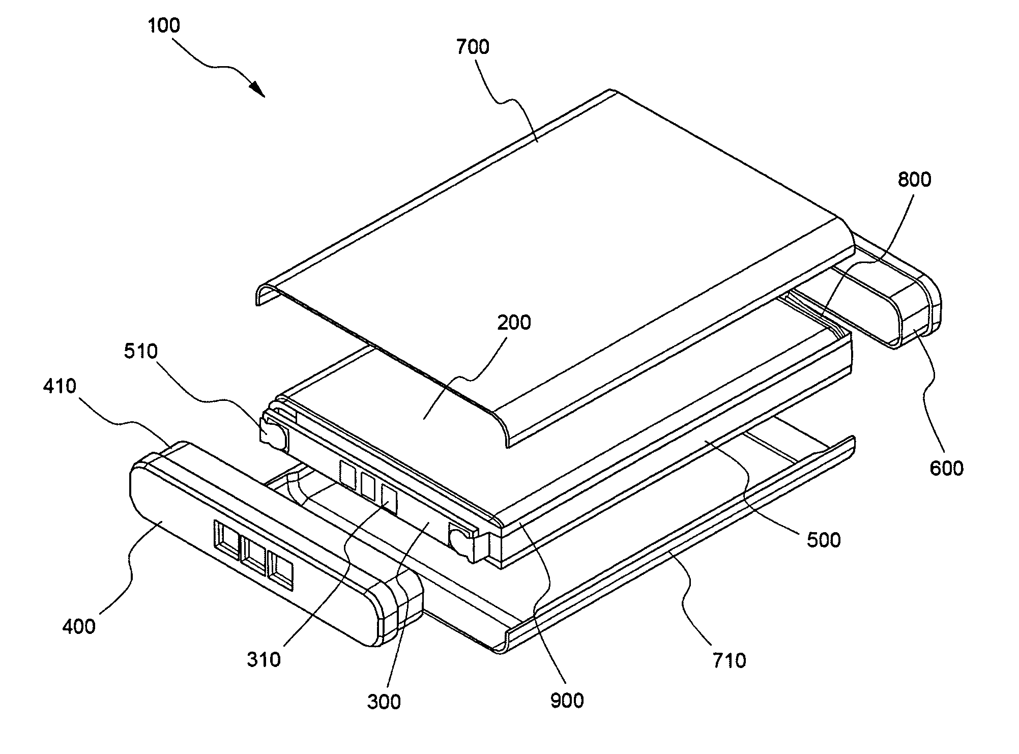
[0055]FIG. 5 schematically shows a partially exploded perspective view of a secondary battery in accordance with one embodiment of the present invention.

[0056] Referring to FIG. 5, the secondary battery 100 is composed of a cell body 200 wherein an electrode assembly of cathode / separator / anode (not shown) is built in a case; a protection circuit 300 for controlling charge / discharge of the battery 100; a cap housing 400 coupled to the upper part of the cell body 200 while including the protection circuit 300; nickel plates 500 and 510 for electrically connecting electrode terminals of the cell body 200 to the protection circuit 300, as electrode leads; a bottom cap 600 coupled to the bottom of the cell body 200; and upper and...


PUM

PropertyMeasurementUnit
electricalaaaaaaaaaa
temperature coefficientaaaaaaaaaa
adhesionaaaaaaaaaa

Abstract

Provided is a secondary battery of an assemble-type structure, comprising: a cell body including an electrode assembly of cathode / separator / anode sealed therein; and a cap assembly including a protection circuit electrically connected to the cell body so as to control overcharge, overdischarge and overcurrent of the battery and a cap housing covering an upper part of the battery, and being detachably coupled to the cell body. In accordance with the present invention, since the cap assembly including the protection circuit, cap housing and the like is assembled detachably from the cell body and electrically connected to and also can be physically firmly fixed to one another, provided are effects capable of greatly reducing the manufacturing process steps of the battery, and solving all the problems associated with use of battery cases and insert injection molding. Therefore, the present invention can reduce battery production costs and rejection rate, facilitate greater ease of re-working upon occurrence of rejection in particular components and realize more efficient automation of the battery manufacturing process.

Description

FIELD OF THE INVENTION [0001] The present invention relates to a battery pack structure, and more particularly to a battery pack structure wherein each structural component of the battery can be detachably assembled without use of separate assembling instruments. BACKGROUND OF THE INVENTION [0002] Chargeable / dischargeable secondary batteries are broadly divided into a hard pack type and inner pack type. A typical example of the hard pack battery is shown in FIG. 1. Referring to FIG. 1, the hard pack battery 10 forms an outer portion of an external device 12 on which the battery 10 is mounted, and thus has advantages such as convenient installation of the battery to the external device (12) upon use. However, this battery type has also problems in that it is relatively expensive and shows less compatibility between various products because the battery case (housing 11) should be designed in compliance with kinds of the corresponding external devices under the condition that the cell ...

Claims


Application Information

Patent Timeline
Patent Type & Authority Applications(United States)
IPC IPC(8): H01M6/50H01M50/15H01M50/166H01M50/574H01M50/588H01M50/593H01M50/595
CPCH01M2/0434H01M2200/106H01M2/34H01M2/0456Y02E60/10H01M50/166H01M50/588H01M50/595H01M50/593H01M50/15H01M50/574
Inventor YOON, SEOG JINJUNG, SUN KWANGKIM, HYUNGCHAN
Owner LG ENERGY SOLUTION LTD
Why Eureka
Try Eureka