Apparatus for retaining magnetic particles within a flow-through cell

a flow-through cell and magnetic particle technology, applied in the field of apparatus for retaining magnetic particles within a flow-through cell, can solve the problems of few magnetic separation systems, relative lack of progress in the development of the means used in the apparatus for handling magnetic particles, and serious drawbacks, so as to achieve rapid automated processing of sample liquids, efficient capture of target molecules, and high effective perfusion of particles

Inactive Publication Date: 2005-09-22
ECOLE POLYTECHNIQUE FEDERALE DE LAUSANNE (EPFL)
View PDF9 Cites 27 Cited by
  • Summary
  • Abstract
  • Description
  • Claims
  • Application Information

AI Technical Summary

Benefits of technology

[0012] In one embodiment, the present invention provides an apparatus and a method by which the magnetic particles retained are homogeneously distributed over the cross-section of the flow-through cell, so that liquid flowing through the flow-through cell flows through the retained particles and a maximum of the surfaces of the particles is contacted by the liquid during that flow, thereby enabling an efficient capture of the target molecules or target particles.
[0013] In another embodiment, the present invention provides an apparatus and a method in which the magnetic particles which serve for capturing target particles carried by a liquid sample which flows through a flow-through cell are so retained therein that they are homogeneously distributed in the interio...

Problems solved by technology

Several systems using magnetic separation and purification process have been developed during the two last decades and have led to a large variety of commercially available apparatus which are miniaturized and automated to some extent, but there has been relatively little progress in the development of the means used in those apparatuses for handling the magnetic particles.
However, o...

Method used


Image

  • Apparatus for retaining magnetic particles within a flow-through cell
  • Apparatus for retaining magnetic particles within a flow-through cell
  • Apparatus for retaining magnetic particles within a flow-through cell

Examples


Embodiment Construction

First Apparatus Example

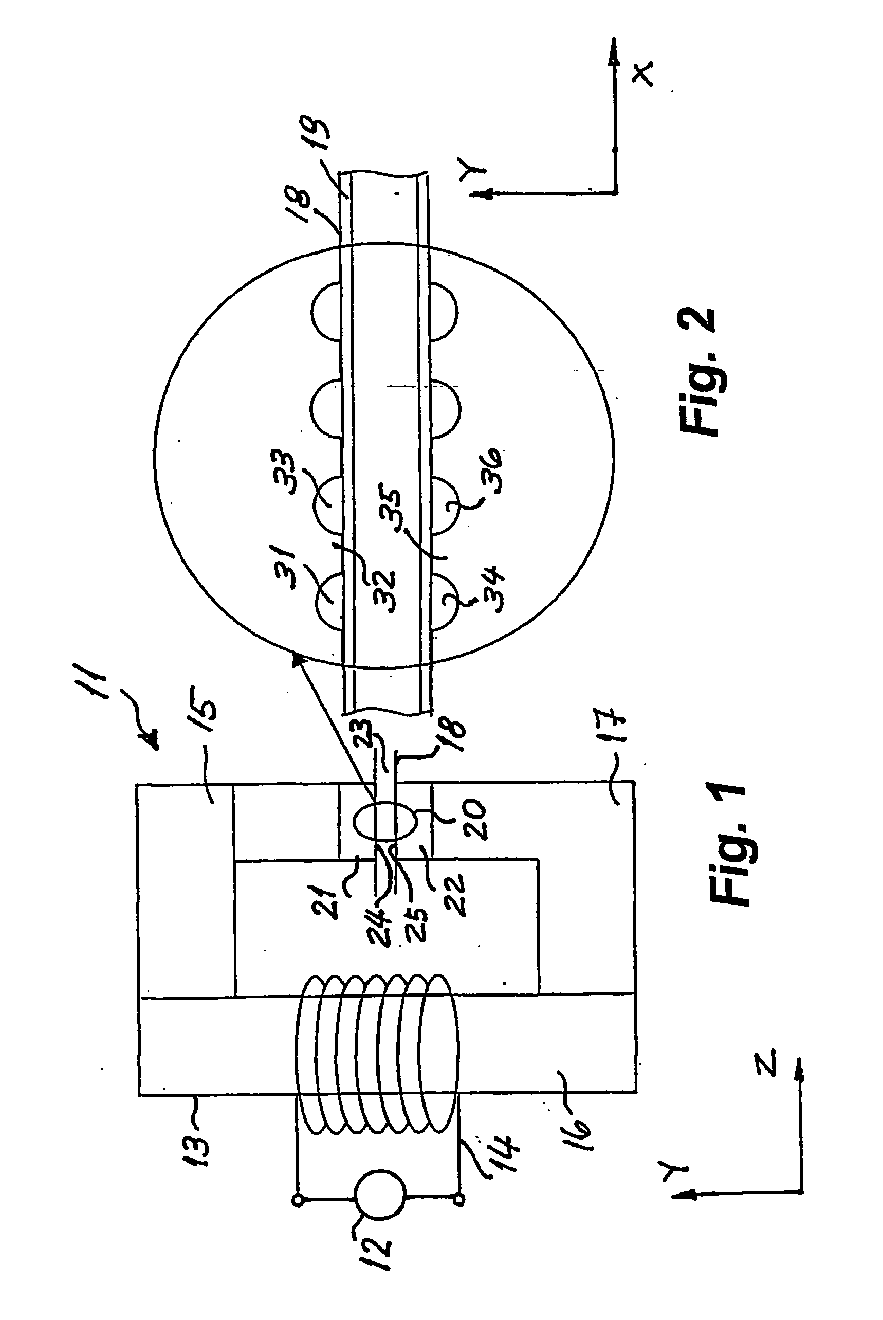
[0036] A first example of an apparatus according to the invention is described hereinafter with reference to FIGS. 1 to 10. FIG. 1 shows a schematic front view of an apparatus according to the invention and also related axis Y and Z. FIG. 2 shows an enlarged side view of zone 20 in FIG. 1 and also related axis X and Y.

[0037] As shown by FIG. 1, an apparatus according to the invention comprises: [0038] (a) optionally, an electrical current source 12; [0039] (b) an electromagnet 13 comprising a winding 14 connected to the current source 12, and [0040] (c) a flow-through cell 18 which is configured and dimensioned to receive an amount of magnetic particles to be retained within a segment of the flow-through cell and to allow flow of a liquid through the flow-through cell.

[0041] In a preferred embodiment the electric current source 12 is a source adapted to provide a current which is variable with time, e.g. an alternating current source adapted to supply a cur...


PUM

PropertyMeasurementUnit
Thicknessaaaaaaaaaa
Thicknessaaaaaaaaaa
Thicknessaaaaaaaaaa

Abstract

An apparatus for retaining magnetic particles within a segment of a flow-through cell during flow of a fluid through the cell comprises (a) optionally, an electrical current source; (b) an electromagnet having a winding connected to the current source and an air gap between at least one pair of poles each of which has a corrugated outer surface and (c) a flow-through cell which is configured and dimensioned to receive an amount of magnetic particles to be retained within the flow-through cell and to allow flow of a liquid through the flow-through cell. The liquid carries molecules or particles to be captured by means of the magnetic particles. A portion of the flow-through cell is inserted in air gap.

Description

FIELD OF THE INVENTION [0001] The invention concerns an apparatus and a method for retaining magnetic particles within a segment of a flow-through cell during flow of a fluid through the cell. [0002] The invention further concerns an apparatus and a method of the above kind which is in addition adapted for manipulating magnetic particles retained within a segment of a flow-through cell during flow of a fluid through the cell. [0003] The invention concerns in particular an apparatus and a method of the above mentioned kinds wherein the magnetic particles are used for capturing target molecules or target particles suspended in and carried by a fluid flowing through a flow-through cell, as is done for instance in clinical chemistry assays for medical diagnostic purposes. The invention further concerns use of an apparatus and a method of the above mentioned kinds in the field of life sciences and in particular for in-vitro diagnostics. BACKGROUND OF THE INVENTION [0004] Magnetic separat...

Claims


Application Information

Patent Timeline
IPC IPC(8): G01N33/53B03C1/035B03C1/28G01N33/553
CPCB03C1/288B03C1/035B03C2201/26B03C1/0335B03C2201/18
Inventor RIDA, AMARELSENHANS, OLIVIERGIJS, MARTINSAVATIC, GORAN
Owner ECOLE POLYTECHNIQUE FEDERALE DE LAUSANNE (EPFL)
Why Eureka
Try Eureka