Expandable intervertebral implant

a technology of intervertebral implants and expandable parts, which is applied in the field of functional spinal implant assemblies, can solve the problems of reducing intervertebral separation, disc damage or disease, and spinal pathologies, and achieves the effect of increasing separation distance and increasing range of angular motion

Inactive Publication Date: 2005-09-22
FLEXUSPINE
View PDF99 Cites 208 Cited by
  • Summary
  • Abstract
  • Description
  • Claims
  • Application Information

AI Technical Summary

Benefits of technology

[0013] In an embodiment, an intervertebral implant may include first and second members having outer surfaces that engage vertebrae of a human spine. The implant may include an insert positioned between inner surfaces of the first and second members before insertion of the implant between the vertebrae. The implant may include an expansion member that increases a separation distance between the first member and the second member. A porti

Problems solved by technology

However, genetic or developmental irregularities, trauma, chronic stress, and degenerative wear can result in spinal pathologies for which surgical intervention may be necessary.
A disc may become damaged or diseased, reducing intervertebral separation.
Reduction of the intervertebral separation may reduce a height of the disc nucleus, which may cause the annulus to buckle in areas where the laminated plies are loosely bonded.
Cages inserted from the posterior approach, however, are limited in size by the interval between the nerve roots.
It should be noted, however, that fusion limits overall flexibility of the spinal column and artificially constrains the natural motion of the patient.
This constraint may cause collateral injury to the patient's spine as additional stresses of motion, normally borne by the now-fused joint, are transferred onto the nearby facet joints and intervertebral discs.
A challenge of instrumenting a disc posteriorly is that a device large enough to contact the end plates and slightly expand the space must be inserted through a limited space.
This challenge is often further heightened by the presence of posterior osteophytes, which may cause “fish mouthing” of the posterior end plates and result in very limited access to the disc.
A further challenge in degenerative disc spaces is the tendency of the disc space to assume a lenticular shape, which requires a relatively larger implant than often is easily introduced without causing tra

Method used


Image

  • Expandable intervertebral implant
  • Expandable intervertebral implant
  • Expandable intervertebral implant

Examples


Embodiment Construction

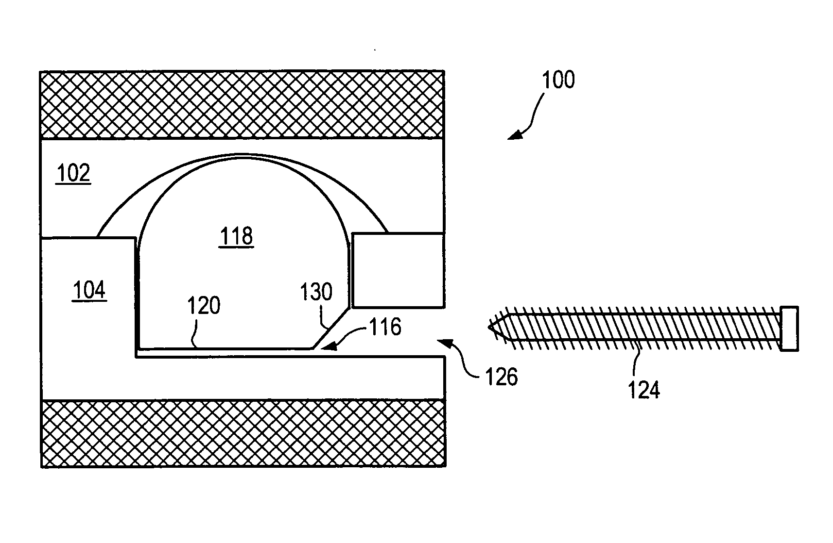
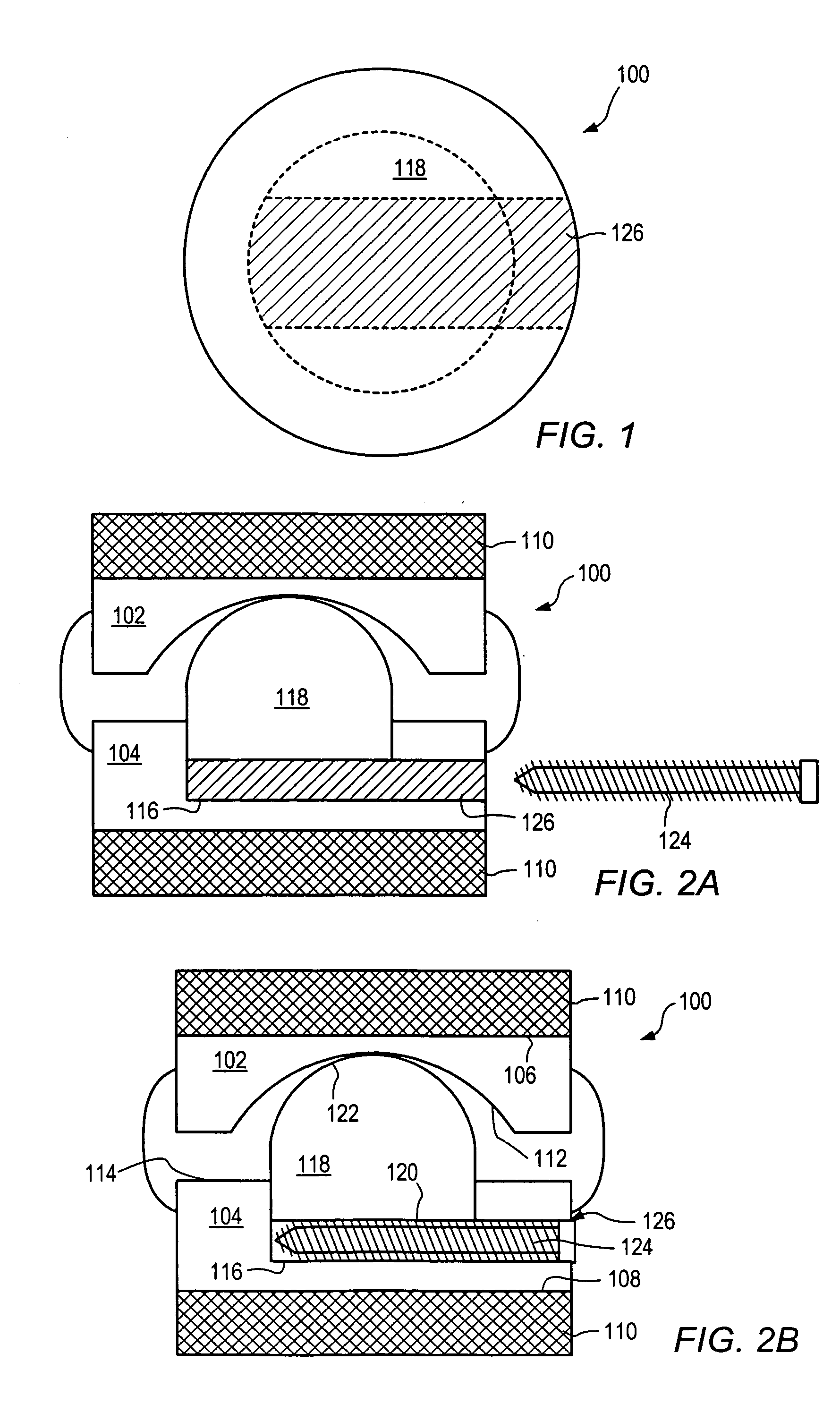
[0137] As used herein, “implant” generally refers to an artificial intervertebral implant or cage. The shape and / or size of an implant or other device disclosed herein may be chosen according to factors including, but not limited to, the surgical approach employed for insertion (e.g., anterior or posterior), the intended position in the spine (e.g., cervical or lumbar), and a size of the patient. For example, cervical implants may range from about 6 mm to about 11 mm in height, and lumbar implants may range from about 10 mm to about 18 mm in height. Heights outside these ranges may be used as required by a patient's anatomy. In general, implants with a substantially round cross section may range from about 14 mm to about 26 mm in diameter, and implants with a substantially square cross section may range from a size of about 14 mm square to a size of about 26 mm square. Implants that are substantially rectangular or trapezoidal may range from about 8 mm to about 12 mm along short sid...


PUM


Abstract

An artificial functional spinal unit including an expandable intervertral implant that can be inserted via a posterior surgical approach and used with one or more facet replacement devices to provide an anatomically correct range of motion is described. Lordotic and non-lordotic expandable, articulating implants and cages are described, along with embodiments of facet replacement devices and instruments for insertion. Methods of insertion are also described.

Description

PRIORITY [0001] This application is a continuation-in-part of U.S. patent application Ser. No. 10 / 634,950 entitled “Artificial Functional Spinal Unit Assemblies” to Charles Gordon and Corey Harbold, filed on Aug. 5, 2003; U.S. patent application Ser. No. 10 / 660,155 entitled “Artificial Functional Spinal Unit Assemblies” to Charles Gordon and Corey Harbold, filed on Sep. 11, 2003, which is a continuation in part of U.S. patent application Ser. No. 10 / 634,950; U.S. patent application Ser. No. 10 / 777,411 entitled “Artificial Spinal Unit Assemblies” to Charles Gordon and Corey Harbold, filed on Feb. 12, 2004, which is a continuation in part of U.S. patent application Ser. No. 10 / 634,950; and PCT Application U.S. 2004 / 025090 entitled “Artificial Spinal Unit Assemblies” to Charles Gordon and Corey Harbold, filed on Aug. 4, 2004, which claims the benefit of U.S. patent application Ser. No. 10 / 634,950, U.S. patent application Ser. No. 10 / 660,155, and U.S. patent application Ser. No. 10 / 777,...

Claims


Application Information

Patent Timeline
IPC IPC(8): A61B17/70A61B17/80A61B17/86A61B17/88A61F2/00A61F2/02A61F2/28A61F2/30A61F2/44A61F2/46
CPCA61B17/7005A61B17/7007A61B17/7008A61B17/701A61B17/7023A61B17/7032A61B17/7037A61B17/7064A61B17/80A61B17/86A61F2/30767A61F2/4405A61F2/4425A61F2/4455A61F2/4611A61F2002/2835A61F2002/30092A61F2002/30131A61F2002/30133A61F2002/30225A61F2002/3023A61F2002/30235A61F2002/30365A61F2002/30369A61F2002/3038A61F2002/30383A61F2002/30462A61F2002/30471A61F2002/30476A61F2002/30492A61F2002/305A61F2002/30505A61F2002/30507A61F2002/30515A61F2002/3052A61F2002/30538A61F2002/3055A61F2002/30556A61F2002/30563A61F2002/30565A61F2002/30578A61F2002/30579A61F2002/30601A61F2002/30626A61F2002/30649A61F2002/30662A61F2002/30772A61F2002/30785A61F2002/30794A61F2002/30841A61F2002/30904A61F2002/443A61F2002/4627A61F2002/4628A61F2002/4629A61F2210/0014A61F2220/0025A61F2220/0033A61F2220/0075A61F2220/0091A61F2230/0013A61F2230/0015A61F2230/0069A61F2250/0006A61F2250/0009A61F2310/00023A61F2002/30331A61F2002/30624A61F2002/3079A61F2002/4622
Inventor GORDON, CHARLES R.HARBOLD, COREY T.HANSON, HEATHER S.
Owner FLEXUSPINE
Why Eureka
Try Eureka