
Apparatus and method for thermally developing flexographic printing sleeves

Active Publication Date: 2005-09-29
MACDERMID PRINTING SOLUTIONS
View PDF16 Cites 21 Cited by
  • Summary
  • Abstract
  • Description
  • Claims
  • Application Information

AI Technical Summary

Benefits of technology

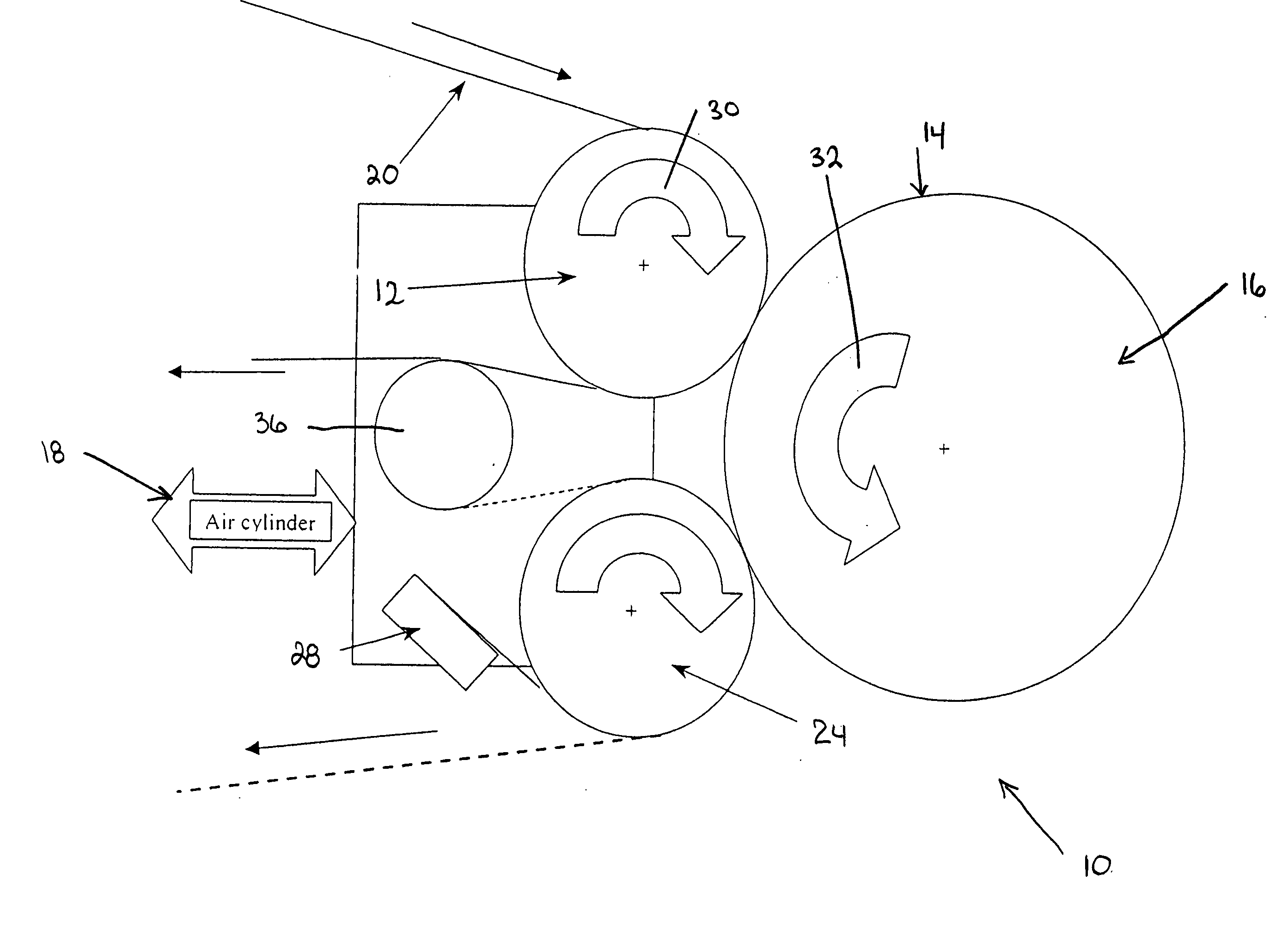
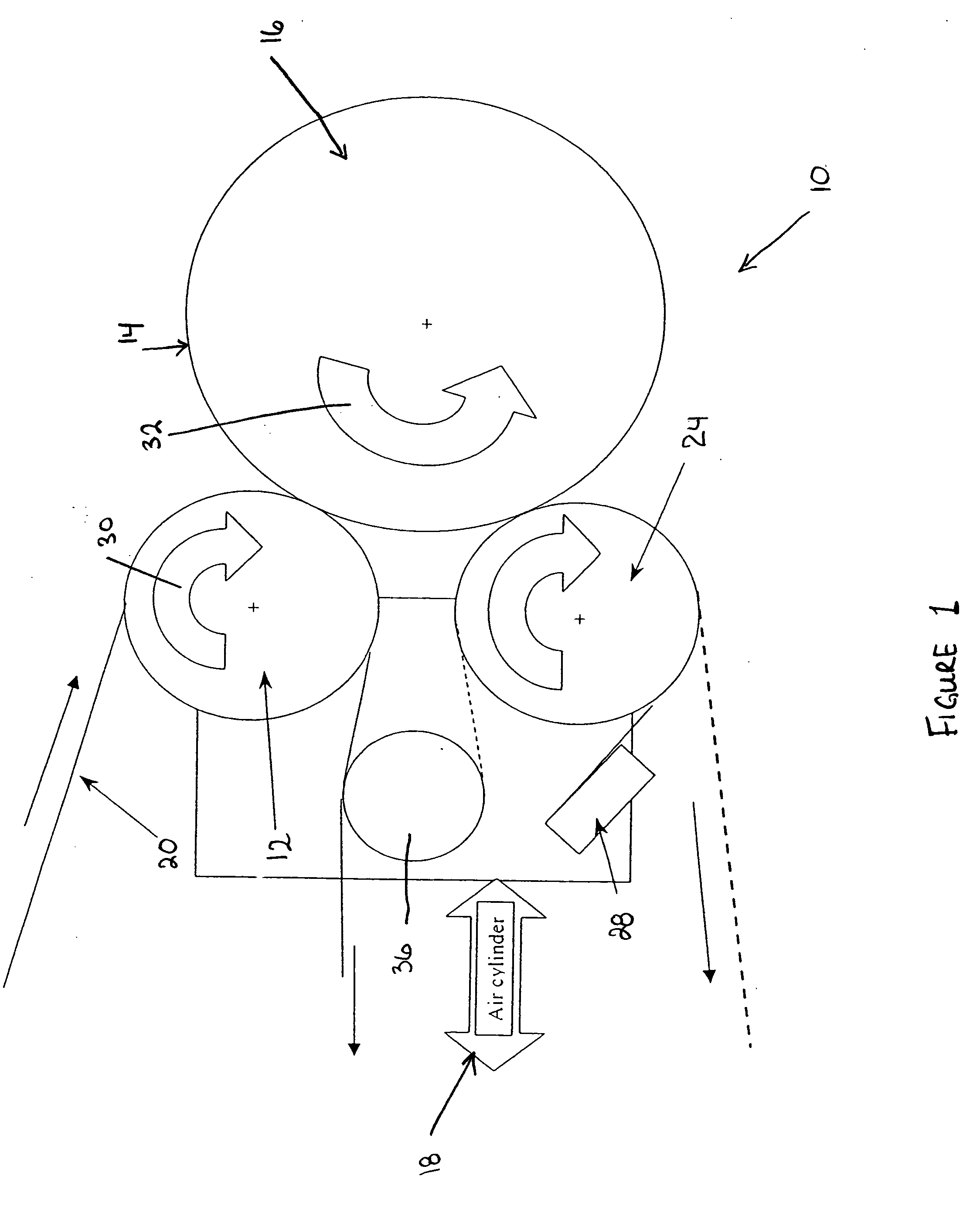
[0029] In another preferred embodiment, one or more additional heatable rolls may be positioned in an opposing position on the opposite side of the cylindrical printing element to increase resin removal from the imaged surface of the flexographic printing element and to increase imaging speed.

Problems solved by technology

The drawback to many of the current methods of thermal development is that these methods can be used only on flat plates, which must then be mounted after development.
This operation requires an additional machine and more time and can also result in a loss in accuracy when registration between multiple plates and colors is required.
This increases the difficulty in making printing elements of different sizes.
In addition, additional problems may arise when attempting to make the blotting machine larger.
Another problem with the current blotting methods is that a tremendous amount of force (approximately 100 pounds / linear inch) must be applied by the heated roll to force the blotting material into the image on the printing element.
This large force can cause the heated roll to bend, resulting in an uneven floor.

Method used


Image

  • Apparatus and method for thermally developing flexographic printing sleeves
  • Apparatus and method for thermally developing flexographic printing sleeves
  • Apparatus and method for thermally developing flexographic printing sleeves

Examples


Embodiment Construction

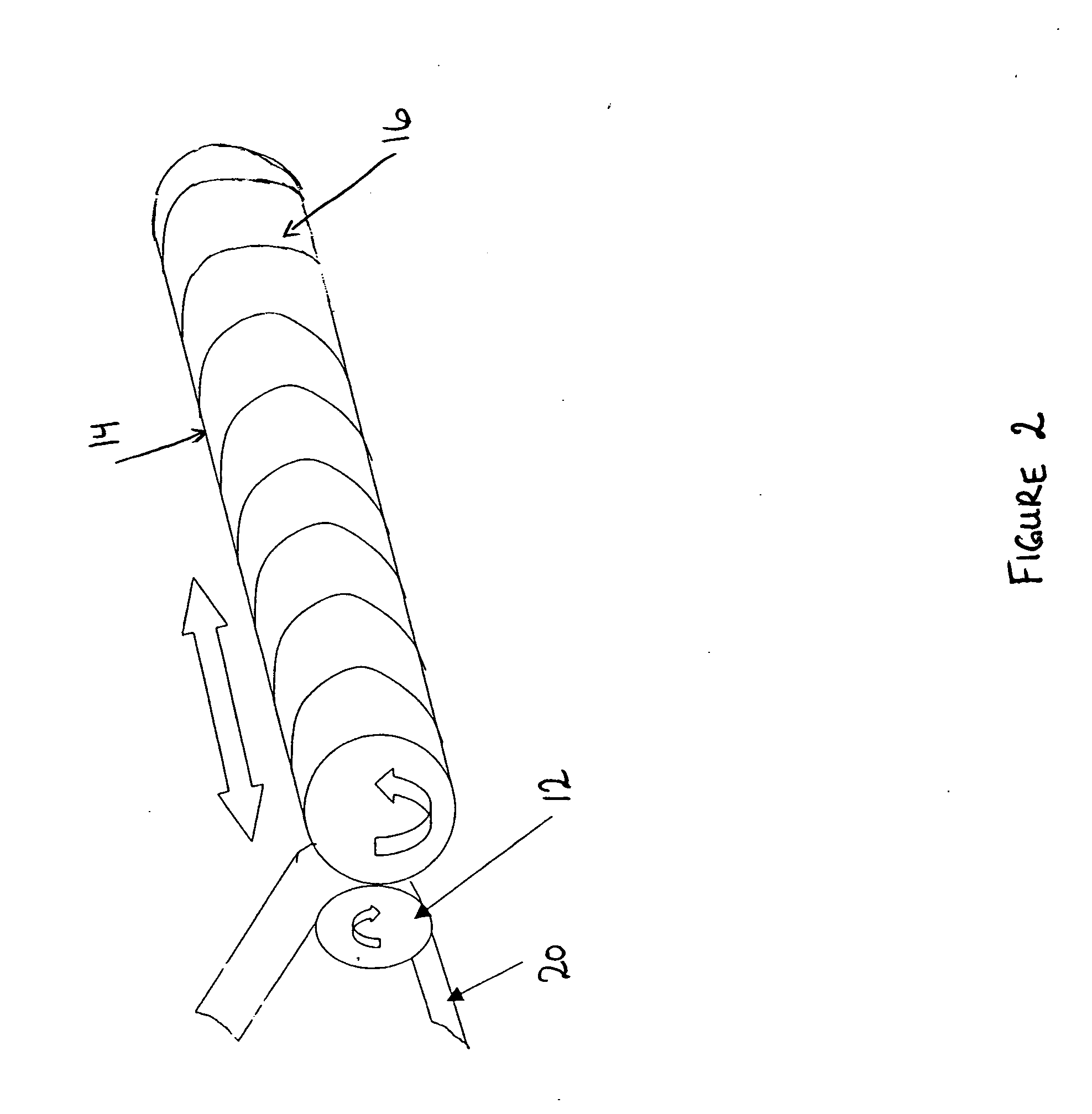
[0037] The present invention relates to an improved thermal development apparatus and a method of using the apparatus to remove non-crosslinked polymer from an imaged surface of a relief image printing element during a process for manufacturing the relief image printing element.

[0038] A flexographic printing element is produced from a photocurable printing blank by imaging the photocurable printing blank to produce a relief image on the surface of the printing element. This is generally accomplished by selectively exposing the photocurable material to actinic radiation, which exposure acts to harden or crosslink the photocurable material in the irradiated areas.

[0039] The photocurable printing blank contains one or more layers of an uncured photocurable material on a suitable backing layer. The photocurable printing blank can be in the form of either a flat, planar element or as a cylindrical printing element.

[0040] The printing element is selectively exposed to actinic radiation...


PUM


Abstract

An improved thermal development apparatus is used to remove uncured photopolymer from the imaged surface of a flexographic printing element. The apparatus typically comprises one or more heatable rolls that are contactable with an imaged surface of a flexographic printing element; and means for maintaining contact between the one or more heatable rolls and the imaged surface of the flexographic printing element. The one or more heatable rolls are heated and is moved over at least a portion of the imaged surface of the flexographic printing element, and non-crosslinked polymer on the imaged surface of the flexographic printing element is melted and removed by the one or more heatable rolls.

Description

FIELD OF THE INVENTION [0001] The present invention is directed to a method and apparatus for thermally developing flexographic printing elements, including printing plates and printing sleeves, which have previously been imaged and / or exposed. BACKGROUND OF THE INVENTION [0002] Flexography is a method of printing that is commonly used for high-volume runs. Flexography is employed for printing on a variety of substrates such as paper, paperboard stock, corrugated board, films, foils and laminates. Newspapers and grocery bags are prominent examples. Coarse surfaces and stretch films can be economically printed only by means of flexography. Flexographic printing plates are relief plates with image elements raised above open areas. Such plates offer a number of advantages to the printer, based chiefly on their durability and the ease with which they can be made. [0003] Although photopolymer printing elements are typically used in “flat” sheet form, there are particular applications and...

Claims


Application Information

Patent Timeline
IPC IPC(8): B41C1/00G03C7/36G03F7/26G03F7/34G03F7/36
CPCG03F7/36G03F7/34
Inventor MARKHART, GARY T.
Owner MACDERMID PRINTING SOLUTIONS
Learn More