Welding torch with plasma assist

a technology of plasma assist and welding torch, which is applied in the direction of welding/cutting media/materials, manufacturing tools, welding apparatus, etc., can solve the problem that the cost of such drive devices can become prohibitiv

Active Publication Date: 2005-09-29
LINCOLN GLOBAL INC
View PDF7 Cites 25 Cited by
  • Summary
  • Abstract
  • Description
  • Claims
  • Application Information

AI Technical Summary

Problems solved by technology

The dielectric discharge becomes more uniform at higher frequencies

Method used


Image

  • Welding torch with plasma assist
  • Welding torch with plasma assist

Examples


Embodiment Construction

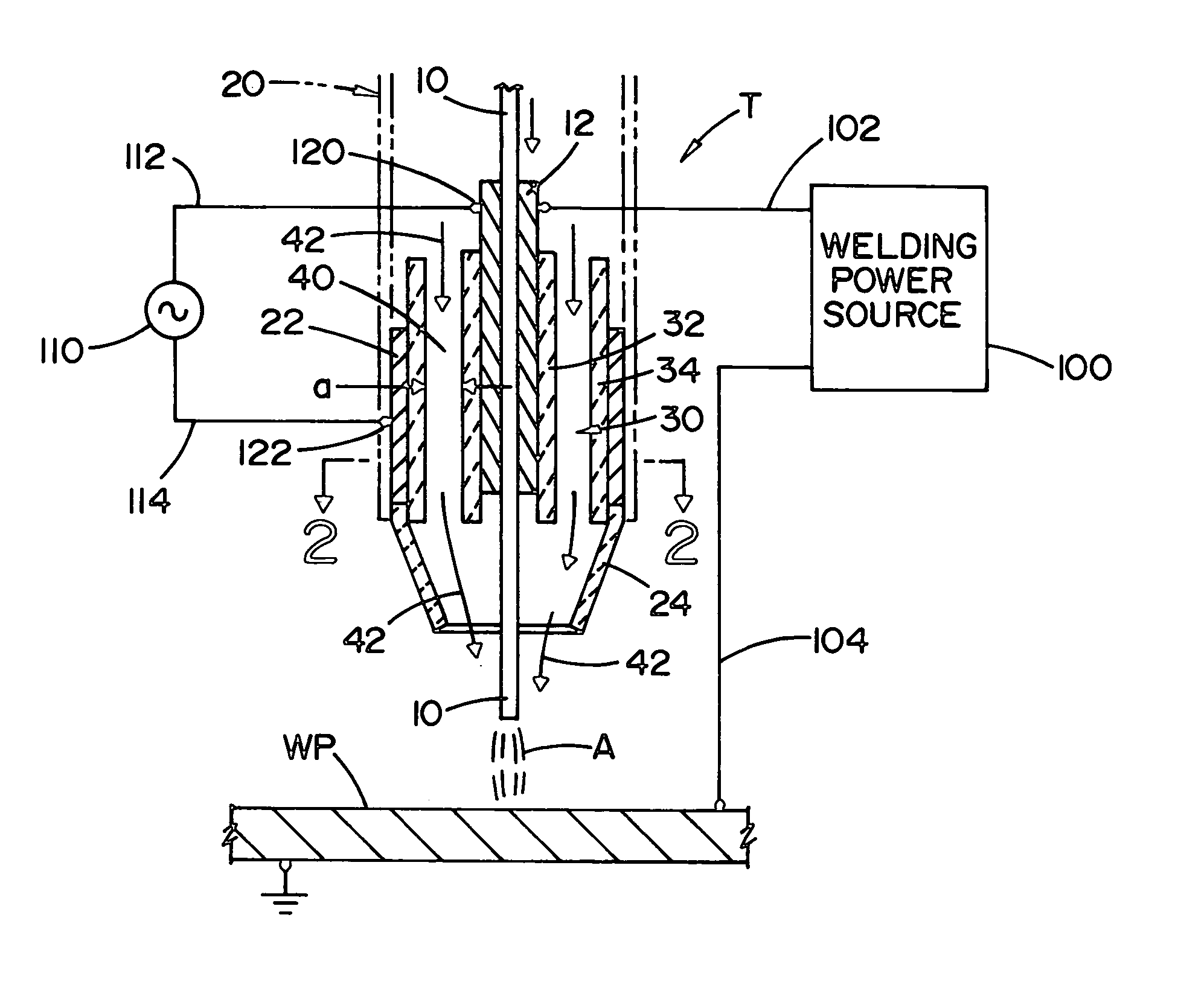
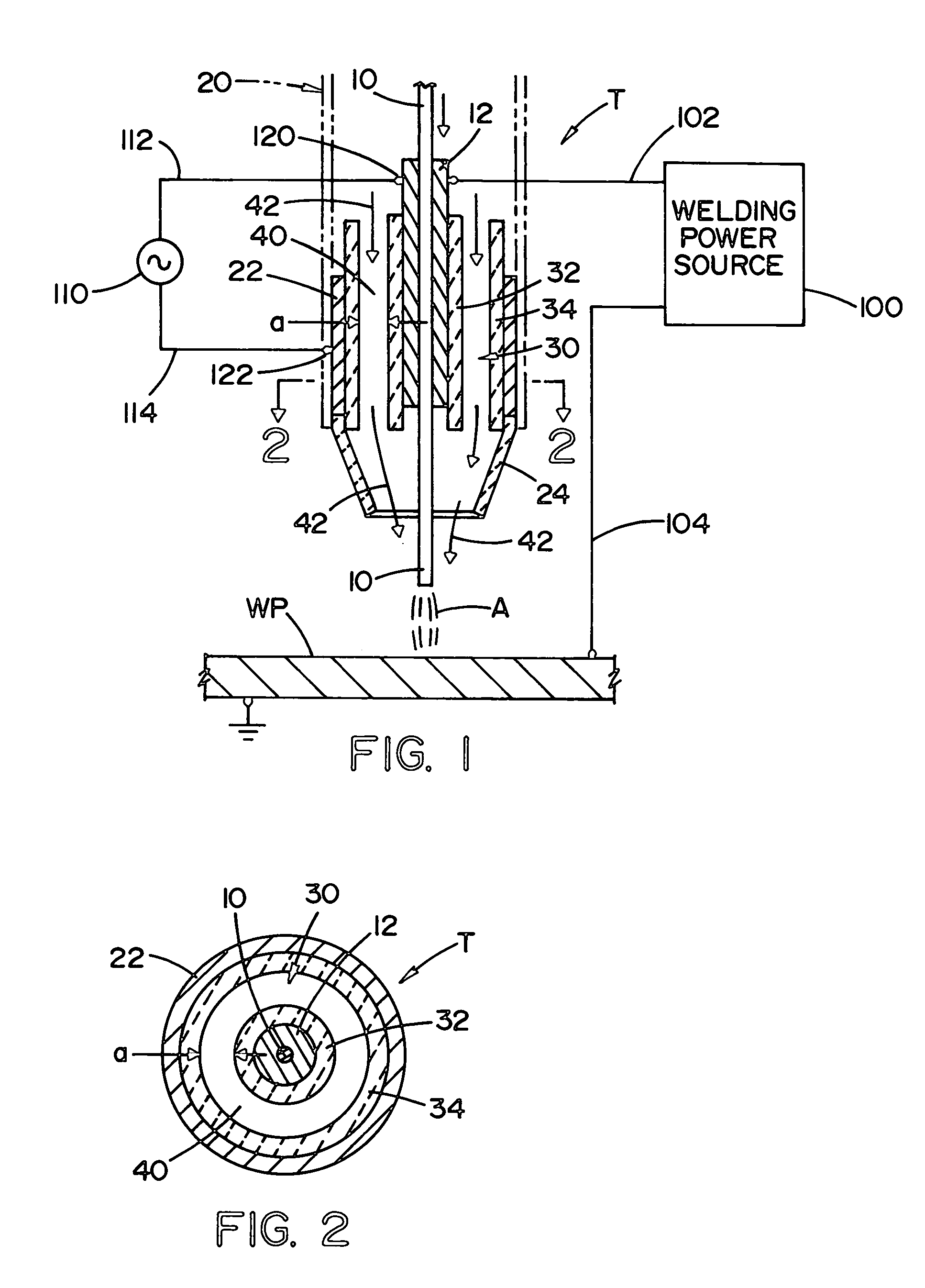
[0015] Referring now to the drawings wherein the showings are for the purpose of illustrating the preferred embodiment of the present invention only, and not for the purpose of limiting same, an electric arc welding torch T is a standard type of torch used in electric arc welding. In accordance with standard technology, wire 10 is driven through contact tip or tube 12 toward workpiece WP, where electrical power causes an arc A between wire 10 and workpiece WP. Contact tip or cylindrical tube 12 is used for electrical contact with moving wire 10. The torch has outer insulated housing 20 illustrated in phantom lines as surrounding a cylindrical conductor or electrode element 22 concentric with and surrounding tip or tube 12 and insulated cup 24 preferably formed of ceramic and extending from housing 20. Conductor 22 is in the form of a cylindrical sleeve defining an annular passageway 30 with tube 12. Passageway 30 includes dielectric sleeves 32, 34 formed from ceramic, glass or polym...


PUM

PropertyMeasurementUnit
Electric potential / voltageaaaaaaaaaa
Widthaaaaaaaaaa

Abstract

An electric arc welding torch having a central conductive contact tube for electrical contact between a power source and a welding wire moving through the contact tube toward a workpiece, a conductive sleeve concentric with the tube to define an annular chamber between the tube and the sleeve, a first dielectric barrier sleeve fixed on the conductive sleeve and a second dielectric sleeve on the tube where the dielectric sleeves are spaced from each other to define an annular gas passage extending around the moving wire and terminals to connect a high frequency power source between the tube and the conductive sleeve to create a dielectric barrier discharge plasma issuing from the gas passage. This torch is used in a novel welding method where the shielding gas envelope around the arc is a plasma.

Description

[0001] The present invention relates to the art of electric arc welding and more particularly to an electric arc welding torch having a plasma assist to enhance the quality of the welding arc. INCORPORATION BY REFERENCE [0002] The present invention relates to an electric arc welding torch wherein the arc shielding gas is directed through a gap or passageway which creates a dielectric barrier discharge plasma formed from the shielding gas forced through the torch. Dielectric barrier discharge creation of a cold plasma is well known in the scientific community. This concept is disclosed in many publications. To provide background information on this electric phenomenon, two articles are incorporated by reference herein. The articles are Cold Plasma Reactor with Dielectric Barrier Discharge by T. Opalinska from the Industrial Chemistry Research Institute of Poland and Dielectric-Barrier Discharges Principle and Applications in the French Journal of Physics (1997). These two articles pr...

Claims


Application Information

Patent Timeline
IPC IPC(8): B23K9/06B23K9/173B23K9/29
CPCB23K9/295B23K9/173H05H1/2406
Inventor BLANKENSHIP, GEORGE D.
Owner LINCOLN GLOBAL INC
Why Eureka
Try Eureka