Dual-walled piping system and methods

a dual-walled, piping technology, applied in the direction of fluid pressure sealing joints, pipe elements, mechanical equipment, etc., can solve the problems of catastrophic failure of such pipelines, high load and great stress, and large stress on the piping segments and, particularly, the connection, so as to reduce stress, minimize heat transfer, and improve load transfer control

Inactive Publication Date: 2005-09-29
OPE INT
View PDF18 Cites 43 Cited by
  • Summary
  • Abstract
  • Description
  • Claims
  • Application Information

AI Technical Summary

Benefits of technology

[0009] The pup joints and bulkheads have a number of features that provide improved load transfer control with resulting reduction of stresses induced by temperature differentials. First, there is a mechanical load-sharing interlock mechanism provided between the bulkhead and the interior pup joint. This mechanism is designed to transmit thermal force loading through a plurality of ridges or threads, that may be enhanced by thermal contraction, and thereby preclude axial movement between the jacket pipe and carrier pipe. A number of methods are described for creating the load-sharing interlock. Additionally, the bulkhead has a generally arcuate cross-section that defines interior channels. The arcuate cross-section allows the bulkhead to be somewhat flexible to absorb axial and radial loading. The cross section also minimizes heat transfer.
[0010] Seal welds between the bulkhead and the pup joints provide the means of isolating the insula...

Problems solved by technology

One longstanding problem with such pipelines is that temperature differentials between the product being piped and the environment cause great stresses upon the piping segments and, particularly, their connections.
In addition, because the inner carrier pipe and the outer jacket pipe of a pipe segment may be exposed to greatly different temperatures, they can each expand and contract in an axial direction placing high loads and great stress upon t...

Method used


Image

  • Dual-walled piping system and methods
  • Dual-walled piping system and methods
  • Dual-walled piping system and methods

Examples


Embodiment Construction

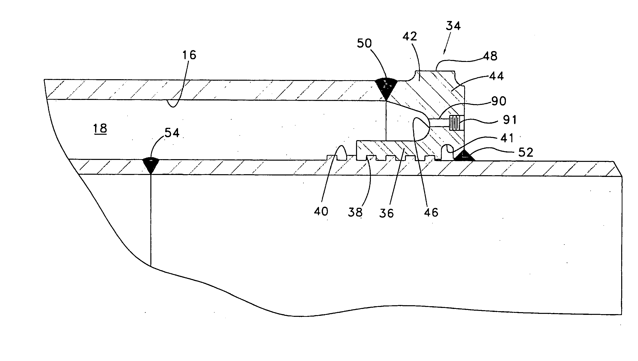
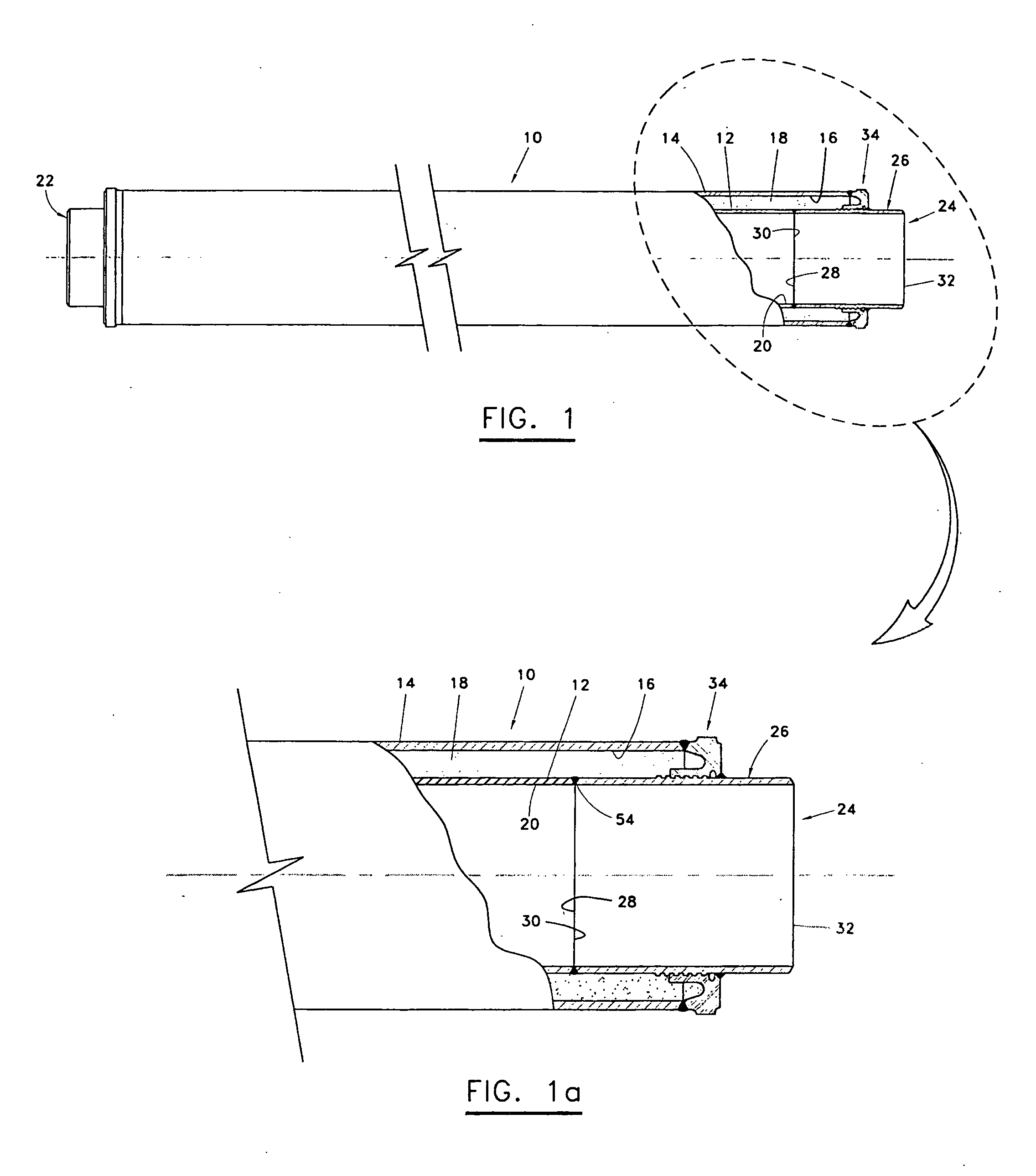
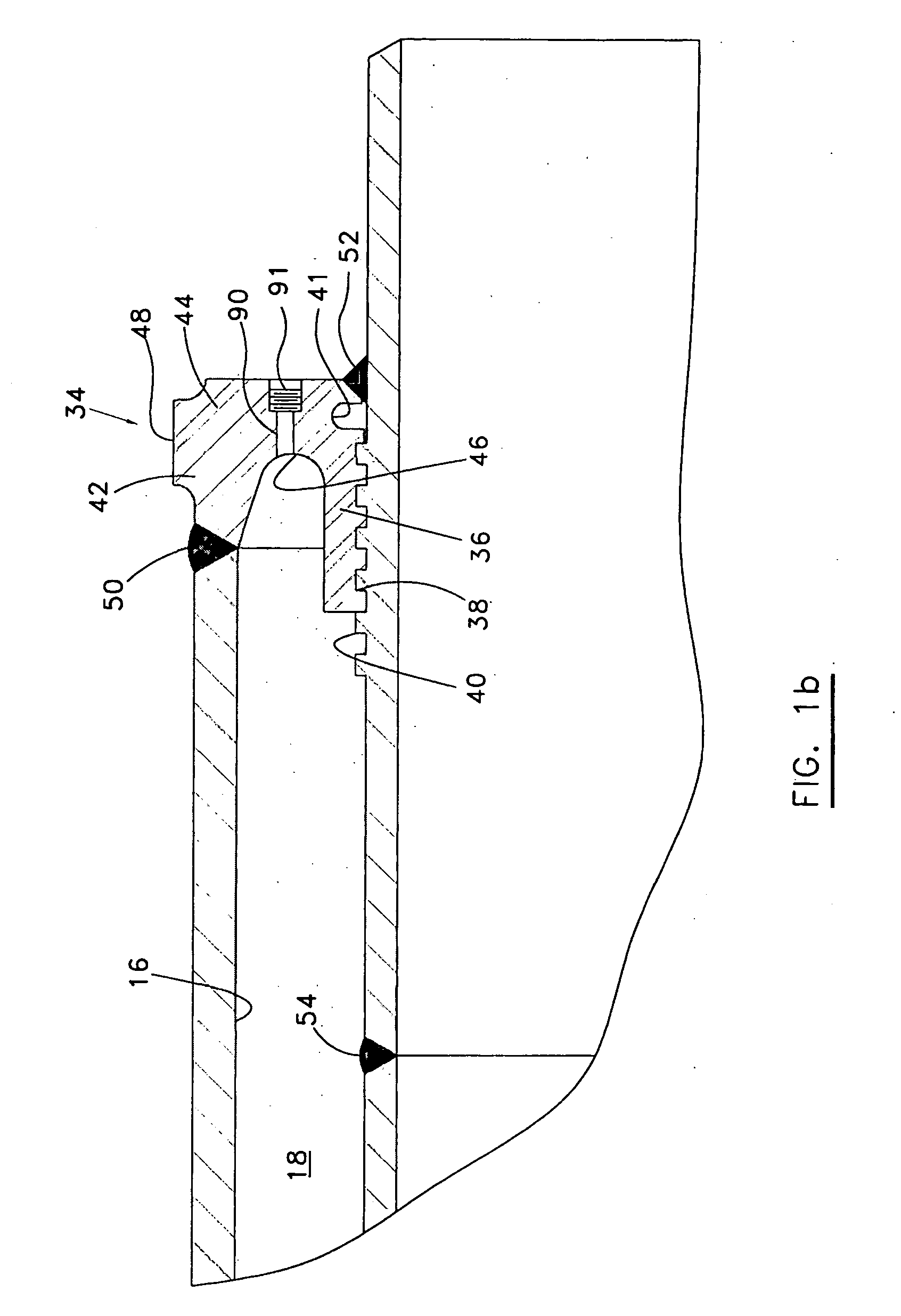
[0027]FIGS. 1, 1a and 1b illustrate an exemplary dual-walled piping segment 10 that of a type used within a piping system to transport extreme temperature fluids. The piping segment 10 includes a radially inner carrier pipe 12 and a radially outer jacket pipe 14. The pipes 12 and 14 are preferably formed of steel alloys and other material suited for the thermal, pressure and corrosion issues as containment barriers. An annulus 16 is defined between the carrier pipe 12 and the jacket pipe 14 and is filled with insulating material 18. The carrier pipe 12 defines an axial fluid flow bore 20 along its length. The piping segment 10 has two axial ends 22, 24, which are preferably identical in construction. Details of the axial end 24 are shown in cross-section in FIGS. 1 and 1a. The end 24 includes a radially inner pup joint 26 that is of similar diameter as the carrier pipe 12 with a first axial end 28 that abuts the axial end 30 of the carrier pipe 12. The second axial end 32 of the pup...


PUM


Abstract

Dual-walled piping segments and pipelines are described that use an annular bulkhead to secure the jacket pipe radially outside of the carrier pipe near the axial ends of the piping segment. Pup joints are welded to each end of the carrier pipe, and the bulkheads are welded to the pup joints. The bulkheads have a number of features that provide improved load path control for axial forces induced by temperature differentials. There is a mechanical load-sharing interlock mechanism provided between the bulkhead and the interior pup joint and field joint closure joints designed to transmit stress loading to a plurality of ridges or threads, that may be enhanced by thermal contraction, and preclude axial movement between the jacket pipe and pup joint. A number of methods are described for creating the load-sharing interlock. Additionally, the bulkhead has a generally arcuate cross-section that defines an interior channel. The arcuate cross-section allows the bulkhead to be somewhat flexible to absorb axial and radial loading while reducing the available heat transfer rate. The bulkhead also contains several ports for pressure equalization and plugged ports for the pressure-thermal-chemical conditioning of the annular spaces.

Description

[0001] This application claims the priority of U.S. provisional patent application Ser. No. 60 / 557,259 filed Mar. 29, 2004.BACKGROUND OF THE INVENTION [0002] 1. Field of the Invention [0003] The invention relates generally to dual-walled piping systems. In particular aspects, the invention relates to details and methods for constructing piping segments and pipelines formed of dual-walled piping segments. [0004] 2. Description of the Related Art [0005] Dual-walled pipelines are often used at great depths in the ocean to carry fluids of extreme temperature. The annulus between the inner and outer pipes is typically filled with insulation to minimize fluctuations in temperature while the fluid is in transit through the pipeline. The pipelines are formed of a number of individual dual-walled piping segments that are interconnected in an end-to-end fashion. [0006] One longstanding problem with such pipelines is that temperature differentials between the product being piped and the enviro...

Claims


Application Information

Patent Timeline
IPC IPC(8): F16L9/14F16L9/18F16L39/00F16L59/14
CPCF16L9/18F16L39/005F16L59/143
Inventor HAUN, RICHARD D.
Owner OPE INT
Why Eureka
Try Eureka