
Oscillator circuit having a temperature dependence

a technology of oscillator circuit and temperature dependence, which is applied in the direction of generator stabilization, modulation, information storage, etc., can solve the problems of increasing power dissipation, consuming battery working as a power supply source, and small margin for the required refresh period, so as to suppress a steep change in the profile of the period

Inactive Publication Date: 2005-09-29
LONGITUDE LICENSING LTD
View PDF3 Cites 6 Cited by
  • Summary
  • Abstract
  • Description
  • Claims
  • Application Information

AI Technical Summary

Benefits of technology

[0013] It is therefore an object of the present invention to overcome the above-mentioned drawbacks by providing an oscillator circuit that generates a refresh period signal specifying a period depending on the sensed temperature, and that can reduce fluctuation of the refresh period along with fluctuation of the sensed temperature, and enlarge the difference between the period generated at a higher temperature and the period generated at a low temperature.
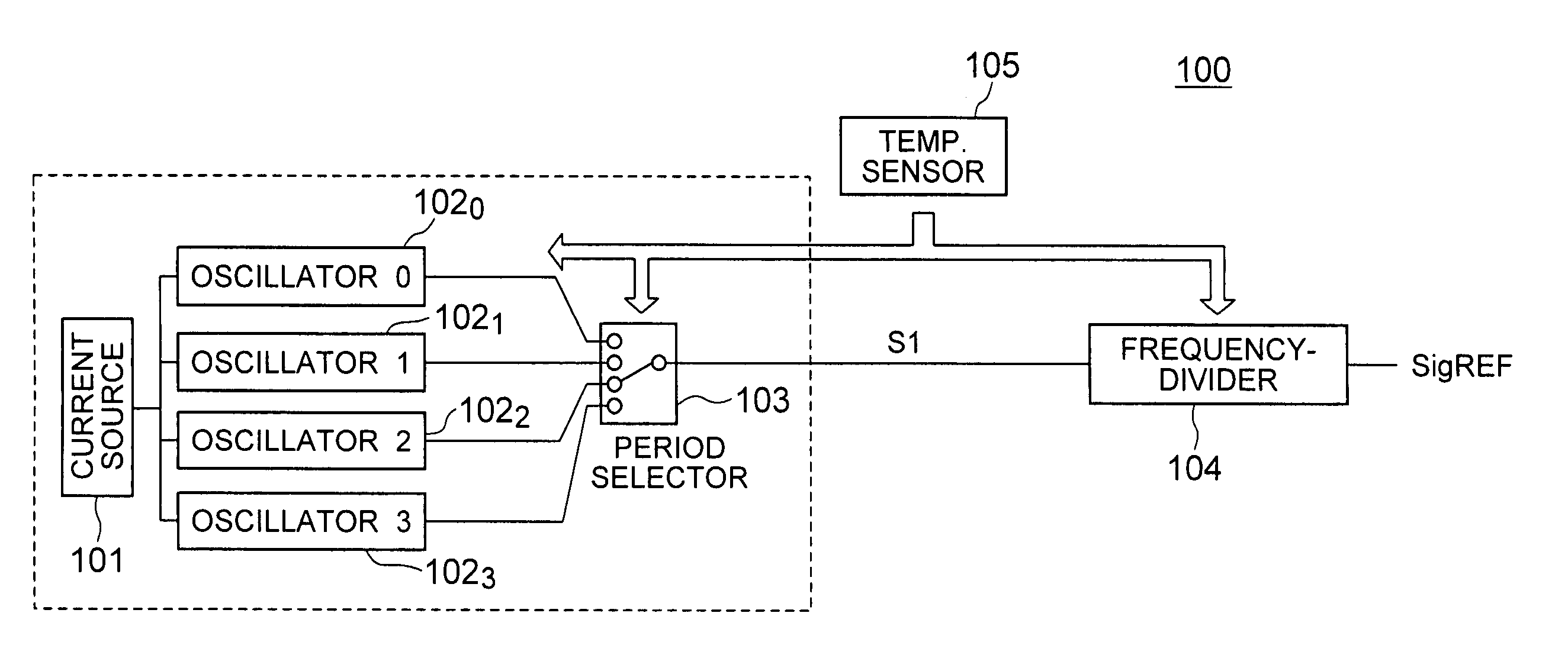
[0015] According to the oscillator circuit of the present invention, a higher ambient temperature sensed by the temperature sensor reduces the frequency dividing ratio selected by the frequency demultiplication circuit, with a result that the period of an output signal therefrom is reduced as the ambient temperature increases. Thus, the period of the output signal can be effectively changed in accordance with the change of the ambient temperature. Furthermore, since the oscillation period of the oscillation circuit changes depending on the change of the ambient temperature, even if the temperature detected by the temperature sensor fluctuates, fluctuation of the period of the output signal can be reduced as compared with the case in which the oscillation circuit does not change the period based on the ambient temperature.
[0026] In the above preferred case, it is assumed here that in each of the respective temperature ranges, the period of an output signal from the oscillation unit at the highest temperature within the temperature range is T0 (fundamental period) and the period of an output signal from the oscillation unit at the lowest temperature within the temperature range is 2×T0 (with the change ratio of the period being at “2” in the temperature range). The frequency dividing ratio within the temperature range may be set at “4” by setting the frequency dividing ratio in an adjacent lower temperature range at “8” and by setting the frequency dividing ratio at an adjacent higher temperature range at “2”, for the purpose of suppressing a steep change in the profile of the period in an output signal from the oscillator circuit around the boundary between the temperature ranges.

Problems solved by technology

In a DRAM, due to an operating current at the time of refresh operation, a battery working as a power supply source is consumed.
As a result, the difference between the graph (A) and the graph (B) becomes small, as shown by a dotted line in FIG. 13B, and there is raised a problem that margin for the required refresh period becomes small.
As a result, the refresh period becomes unnecessarily short, thereby raising a problem of increased power dissipation.
Conversely, if the current value at a low temperature is set higher so as to secure the effective operation at the low temperature, there is raised a problem that the power dissipation is increased at a higher temperature.
Thus, when employing the analog system, actually, the refresh period cannot be effectively changed, and the change ratio of the refresh period of the analog system is generally suppressed to approximately several times at a maximum.
Accordingly, in the analog system, when the chip temperature is low, there is raised a problem that a large difference is caused between the required refresh period (graph (A) in FIG. 14B) and the refresh period specified by the refresh period signal SigREF (graph (B)) output from the frequency demultiplication circuit 203a.

Method used


Image

  • Oscillator circuit having a temperature dependence
  • Oscillator circuit having a temperature dependence
  • Oscillator circuit having a temperature dependence

Examples


first embodiment

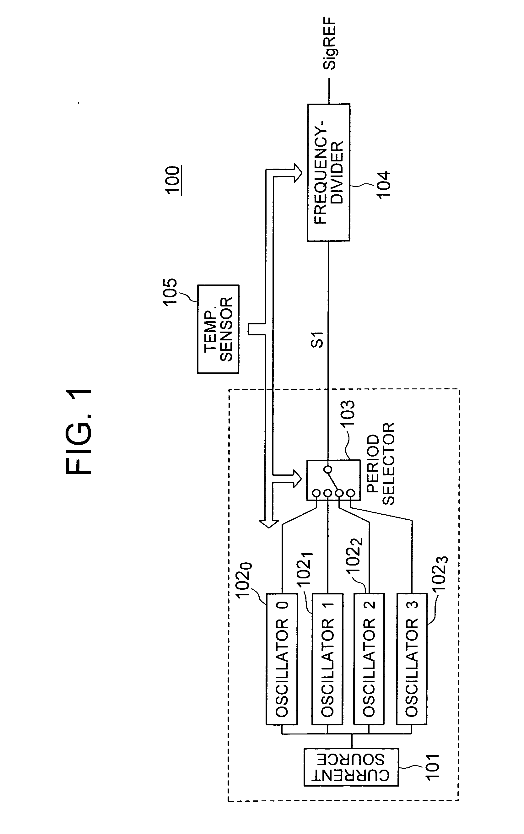
[0041] The oscillator circuit according to the present invention will further be described below with reference to the accompanying drawings. FIG. 1 shows a block diagram of an oscillator circuit 100 according to the present invention. As shown in FIG. 1, the oscillator circuit 100 includes a current source 101, oscillators 1020 to 1023, a period selecting circuit (oscillator selection unit) 103, a frequency demultiplication circuit 104, and a temperature sensor 105. The current source 101, oscillators 1020 to 1023, and period selecting circuit 103 in combination configure an oscillation unit. The oscillator circuit 100 may be mounted together with DRAM memory cells on a chip on which a general-purpose DRAM, a pseudo-SRAM, or a system LSI is arranged.

[0042] The current source 101 delivers a current having a current value depending on the ambient temperature. Specifically, a lower temperature provides a lower output current delivered from the current source 101. Each of the oscillato...

second embodiment

[0057]FIG. 8 shows a block diagram of an oscillator circuit 100a according to the present invention. The second embodiment is similar to the first embodiment except that the refresh period signal SigREF specifying a period which changes depending on the ambient temperature is generated using a plurality of current sources 101a0 to 101a3 and a single oscillator 102.

[0058] The current sources 101a0 to 101a3, a period selecting circuit 103a, and the oscillator 102 in combination configure an oscillation unit. Each of the current sources 101a outputs a current depending on the ambient temperature. The period selecting circuit (current source selection unit) 103a selects one of the plurality of current sources 101a in accordance with the temperature ranges based on the ambient temperature sensed by the temperature sensor 105, and supplies a current generated by the selected current source 101a to the oscillator 102. The relations between the current values of the respective current sourc...


PUM


Abstract

An oscillator circuit includes a current source for generating a current depending on the ambient temperature, a plurality of oscillators for oscillating at respective periods depending on the current from the current source and based on different relations between the ambient temperature and the periods, and a frequency demultiplication unit for receiving an output signal from one of the oscillators selected by a period selecting circuit 103. The frequency dividing ratio of the frequency demultiplication circuit is set so that a higher ambient temperature provides a smaller frequency dividing ratio.

Description

BACKGROUND OF THE INVENTION [0001] 1. Field of the Invention [0002] The present invention relates to an oscillator circuit having a temperature dependence, and more particularly, to an oscillator circuit that changes the period of an output signal depending on on the ambient temperature. [0003] 2. Description of Related Art [0004] Recently, portable devices such as notebook-size personal computers are provided with a DRAM (Dynamic Random Access Memory) of large capacity so as to store therein a large amount of process data. In a DRAM, since the data retained by respective memory cells are being lost as time elapses, it is necessary to refresh the DRAM before the retained data are lost. [0005] In a DRAM, due to an operating current at the time of refresh operation, a battery working as a power supply source is consumed. Generally, data retention property of a memory cell has a temperature dependency. That is, a lower chip temperature increases the data retention period, thereby raisi...

Claims


Application Information

Patent Timeline
Patent Type & Authority Applications(United States)
IPC IPC(8): G11C11/406H03L1/02H03L1/00
CPCG11C11/406G11C2211/4061G11C11/40626
Inventor HASHIMOTO, TAKESHI
Owner LONGITUDE LICENSING LTD
Learn More