Method and apparatus for improving the efficiency and accuracy of RFID systems

a technology of rfid system and efficiency improvement, applied in the direction of digital computer details, instruments, electromagnetic radiation sensing, etc., can solve the problems of unintelligible reader's accuracy, current rfid system is not suited for precise positioning of tags, transmissions from tags are scrambled and become unintelligible to the reader, etc., to prevent leakage of data signals and improve the efficiency of rfid systems

Active Publication Date: 2005-09-29
SEKNION
View PDF59 Cites 95 Cited by
  • Summary
  • Abstract
  • Description
  • Claims
  • Application Information

AI Technical Summary

Benefits of technology

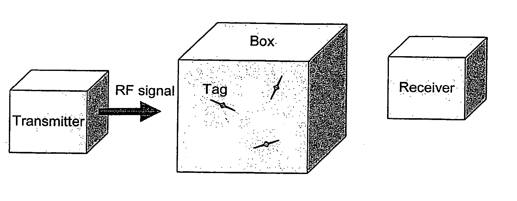
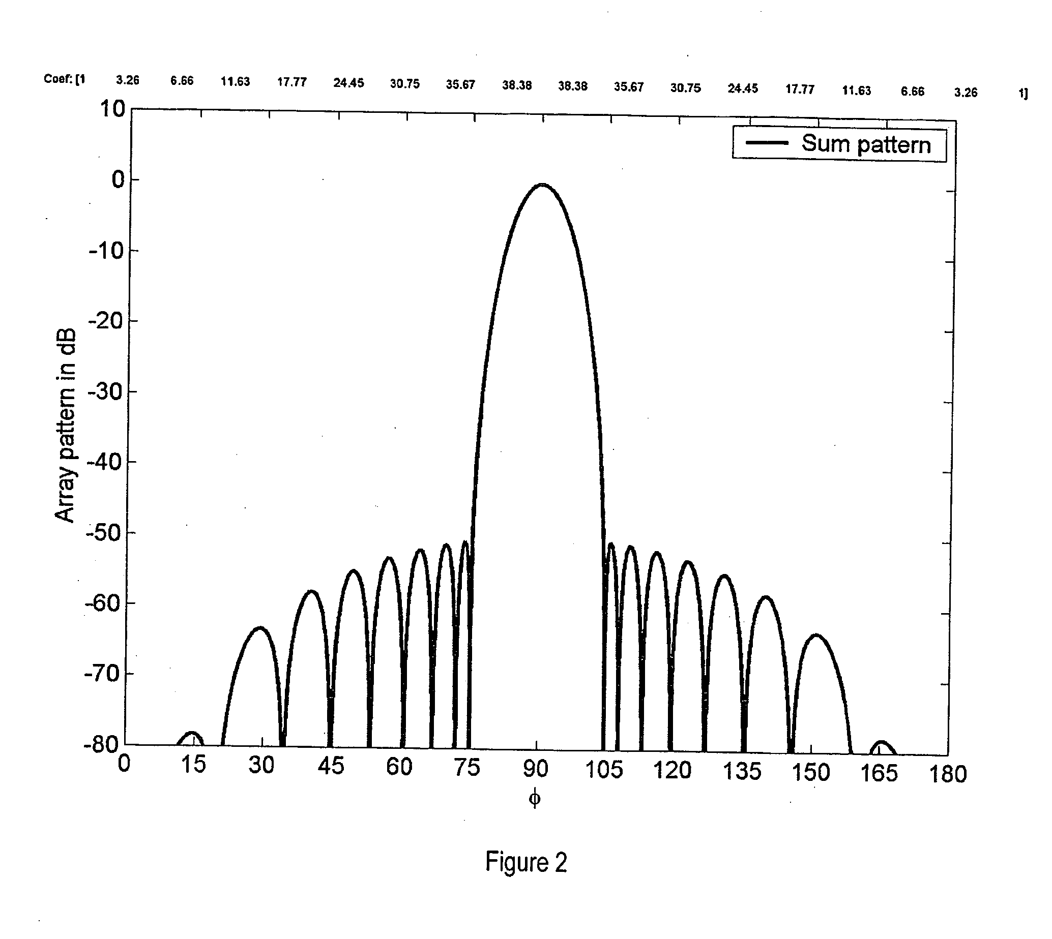
[0021] The present invention is additionally directed to methods for improving the efficiency of RFID systems. In one embodiment of the present invention, the reader employs two antennas that broadcast both data and scramble signals. In one embodiment of the present invention, the antennas are patch antennas. In one embodiment of the present invention, the reader employs three antenna elements where two of them transmit the scramble signal and one interrogates the tags. In one embodiment of the present invention, the reader employs one standard commercially available reader and two additional antennas that broadcast a scramble signal. In one embodiment of the present invention, the array excitation coefficients for the data and scramble signals are adjusted to create an interrogation beam that precisely fits an opening in a container.
[0022] In one embodiment of the present invention, the reader employs an antenna that transmits two or more interrogation beams designed such that any tag in the interrogation zone receives sufficient power to operate from at least one of the interrogation beams. In one embodiment of the present invention, the reader employs two or more scramble beams to prevent leakage of the data signal. In one embodiment of the present invention, two sets of scramble-beam coefficients are mirror images.

Problems solved by technology

Current RFID systems are not suited for precise location of tags because readers transmit very broad beams that cause tags in a large region to respond.
Moreover, when two or more tags respond simultaneously, the transmissions from the tags get scrambled and become unintelligible to the reader.
The accuracy of today's readers is not acceptable for many applications, which require 100 percent accuracy.
According to the article “RFID will present a stiff test,” published in Supply Chain Management Review, Jan. 15, 2004, the main cause of low reader accuracy is the inability of readers to transmit enough power to activate tags that are surrounded by other objects such as tags affixed to items stored in the middle of a pallet.
The problem of reader collisions is another barrier to the large-scale deployment of RFID.
Reader collisions can occur when the interrogation zones of two or more readers overlap.
In the article “Why UHF RFID Systems Won't Scale,” RFID Journal, July 2004, H. L. van Eeden states that “The main technical problem facing end-user companies is the possibility of large-scale reader interference that could render UHF RFID installations completely inoperable and severely limit the rollout of UHF RFID systems.”
The problems of reader collision and low reader accuracy are related: if one attempts to solve the problem of low reader accuracy by increasing the reader power, then the interrogation zones grow and reader collisions become more frequent.

Method used


Image

  • Method and apparatus for improving the efficiency and accuracy of RFID systems
  • Method and apparatus for improving the efficiency and accuracy of RFID systems
  • Method and apparatus for improving the efficiency and accuracy of RFID systems

Examples


Embodiment Construction

[0075] The present invention provides (a) designs for RFID readers, (b) a method for reducing the width of the interrogation region, (c) a method for providing a user defined interrogation zone for one or more readers, (d) a method for location of transceivers in 2D and 3D using more than one information-steering transmitter, (e) a method for precise tag location that works in the induction regime where the wavelength is much longer than the physical dimensions involved, (f) a new set of security measures for RFID systems, (g) a method for optically displaying the interrogation zone, (h) a method for overcoming multipath effects, (i) a method for optimal tag placement, and (j) a bistatic RFID reader. A common feature in items (a)-(f) is that two or more signals are transmitted simultaneously, including: [0076] 1. A data signal that causes the tags to respond. The data signal may instruct the tags to broadcast or modify stored information. The data signal may contain information abou...


PUM


Abstract

The present invention relates to a method and apparatus for transmitting a narrow signal beam that allows the precise location of RFID tags to be determined and reduces tag collisions. The present invention further relates to a method and apparatus for combing an RFID reader with an optical source to visualize the interrogation zone of the reader. The present invention also relates to a method and apparatus for improving the efficiency of RFID systems.

Description

CROSS-REFERENCE TO RELATED APPLICATIONS [0001] This application claims the benefit of U.S. Provisional Application No. 60 / 550,355, filed Mar. 5, 2004, U.S. Provisional Application No. 60 / 550,411, filed Mar. 5, 2004, U.S. Provisional Application No. 60 / 561,433, filed Apr. 12, 2004, U.S. Provisional Application No. 60 / 603,531, filed Aug. 20, 2004, and U.S. Provisional Application No. 60 / 613,428, filed Sep. 27, 2004, each of which is hereby incorporated by reference in its entirety.BACKGROUND OF THE INVENTION [0002] Radio Frequency Identification (“RFID”) is a generic term for technologies that use radio waves to automatically identify individual items. Objects can be identified using RFID by storing a serial number that identifies the object on a chip that is attached to an antenna. The chip and the antenna together are called an RFID tag. An RFID reader sends out electromagnetic waves that are received by the antenna on the RFID tag. Passive RFID tags draw power from this electromagn...

Claims


Application Information

Patent Timeline
Patent Type & Authority Applications(United States)
IPC IPC(8): G06K7/00G06K7/10H04K3/00H04Q5/22
CPCG06K7/0008G06K7/10079H04K2203/32H04K3/825H04K2203/20H04K3/43
Inventor HANSEN, THORKILDORISTAGLIO, MICHAEL L.
Owner SEKNION
Why Eureka
Try Eureka