Exposure apparatus and method

a technology of exposure apparatus and a camera, applied in the field of exposure apparatus and a method, can solve the problems of the transfer accuracy is deteriorated, and achieve the effect of effectively removing air bubbles and preventing the deterioration in the transfer accuracy

Inactive Publication Date: 2005-09-29
CANON KK
View PDF3 Cites 292 Cited by
  • Summary
  • Abstract
  • Description
  • Claims
  • Application Information

AI Technical Summary

Benefits of technology

[0008] The present invention is directed to an exposure apparatus capable of effectively removing the air bubbles that exists in the fluid, and prevents the deterioration in the transfer accuracy.

Problems solved by technology

In detail, even if the vibration level by the ultrasonic wave is large, the transfer image on the wafer is blurred by the vibration and the transfer accuracy is deteriorated.
Also, the error is caused by the vibration at the alignment detection in the XY direction and the focus detection in the Y direction, the overlapping error because of the alignment error and the image blur because of the focus error are generated, and the deterioration in the transfer accuracy is caused.

Method used


Image

  • Exposure apparatus and method
  • Exposure apparatus and method
  • Exposure apparatus and method

Examples


Embodiment Construction

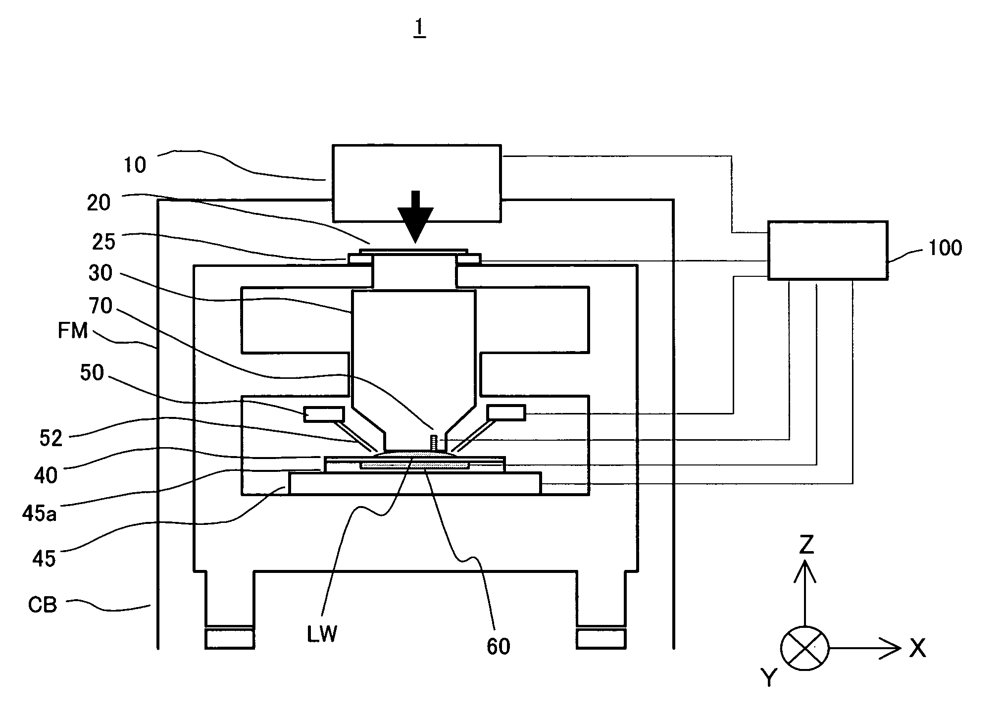
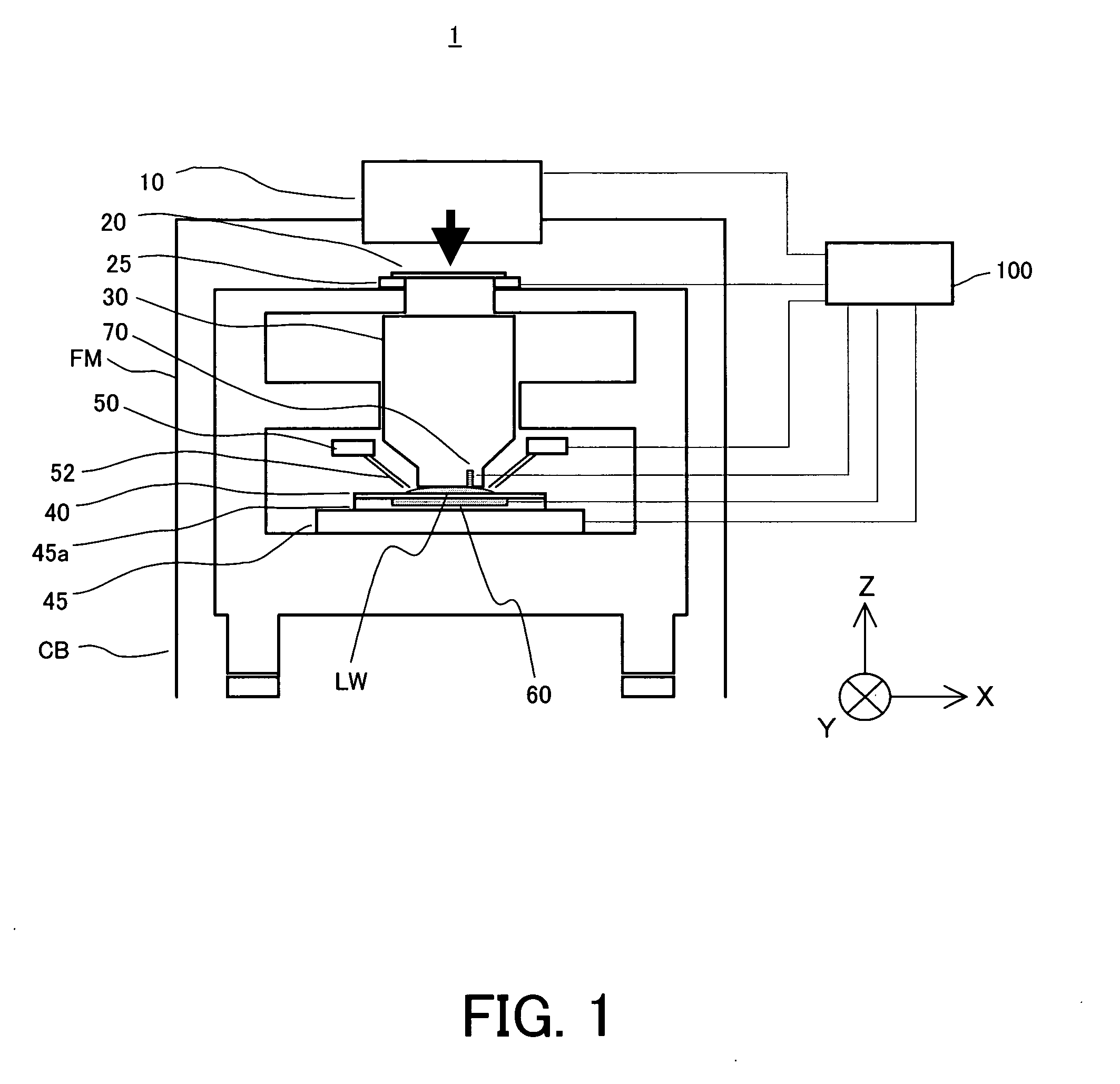
[0021] With reference to the accompanying drawings, a description will be given of an exposure apparatus 1 of one embodiment according to the present invention. In each figure, the same reference numeral denotes the same element. Therefore, duplicate descriptions will be omitted. FIG. 1 is a schematic sectional view of an exposure apparatus 1.

[0022] The exposure apparatus 1 is an immersion type exposure apparatus (an immersion lithography exposure system) that exposes onto an object 40 a circuit pattern created on a reticle 20 via a fluid LW supplied between a final surface at the object 40 side of a projection optical system 30 and the object 40 in a step-and-scan manner. The “step-and-scan manner”, as used herein, is an exposure method that exposes a reticle pattern onto a wafer by continuously scanning the wafer relative to the reticle, and by moving, after an exposure shot, the wafer stepwise to the next exposure area to be shot.

[0023] The exposure apparatus 1 includes, as sho...


PUM

PropertyMeasurementUnit
wavelengthaaaaaaaaaa

Abstract

An exposure apparatus includes a projection optical system for projecting an image of a pattern of a reticle onto an object, via a fluid that is filled in a space between said projection optical system and the object, a vibrator part for vibrating at least one of the fluid, the object, and the projection optical system, and a controller for controlling the vibrator part so that the vibration of at least one of the fluid, the object, and the projection optical system becomes a tolerance during a processing of the object.

Description

BACKGROUND OF THE INVENTION [0001] The present invention relates generally to an exposure apparatus and method used to fabricate various device including semiconductor chips such as ICs and LSIs, display devices such as liquid crystal panels, sensing devices such as magnetic heads, and image pickup devices such as CCDs, as well as fine patterns used for micromechanics, and more particularly to an immersion exposure apparatus (an immersion lithography exposure system) and method for exposing the object through the fluid between the projection optical system and the object. [0002] A projection exposure apparatus has been conventionally used to transfer a circuit pattern on a reticle (or a mask) via a projection optical system onto a wafer etc, and the high-quality exposure at a high resolution has recently been increasingly demanded. The immersion exposure attracted people's attentions as one means that satisfies this demand. The immersion exposure promotes the higher numerical apertu...

Claims


Application Information

Patent Timeline
Patent Type & Authority Applications(United States)
IPC IPC(8): G03F7/20G03B27/42H01L21/027
CPCG03F7/70341G03B27/42B60P7/02B60Y2200/30B61D3/16B61D39/003
Inventor KITAOKA, ATSUSHI
Owner CANON KK
Why Eureka
Try Eureka