Optical transmission systems including optical amplifiers and methods of use therein

a technology of optical amplifiers and optical transmission systems, applied in the direction of transmission, electromagnetic transmission, lasers, etc., can solve the problems of high cost of electrical signal regeneration/amplification equipment, not being deployed in commercial systems, and not initially deployed in optical wdm systems, etc., to improve control, flexibility, and upgradability. , the effect of increasing the control of optical systems

a technology of optical amplifiers and optical transmission systems, applied in the direction of transmission, electromagnetic transmission, lasers, etc., can solve the problems of high cost of electrical signal regeneration/amplification equipment, not being deployed in commercial systems, and not initially deployed in optical wdm systems, etc., to improve control, flexibility, and upgradability. , the effect of increasing the control of optical systems

US20050213985A1Inactive Publication Date: 2005-09-29OPTIC153 LLC

Image

  • Optical transmission systems including optical amplifiers and methods of use therein
  • Optical transmission systems including optical amplifiers and methods of use therein
  • Optical transmission systems including optical amplifiers and methods of use therein

Examples


Embodiment Construction

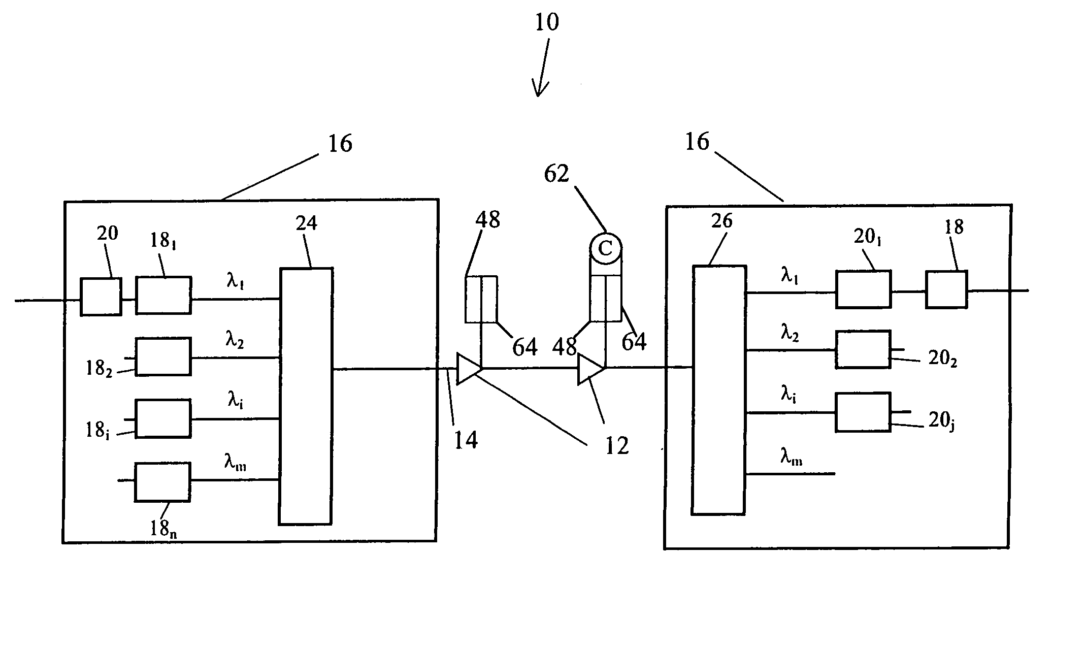
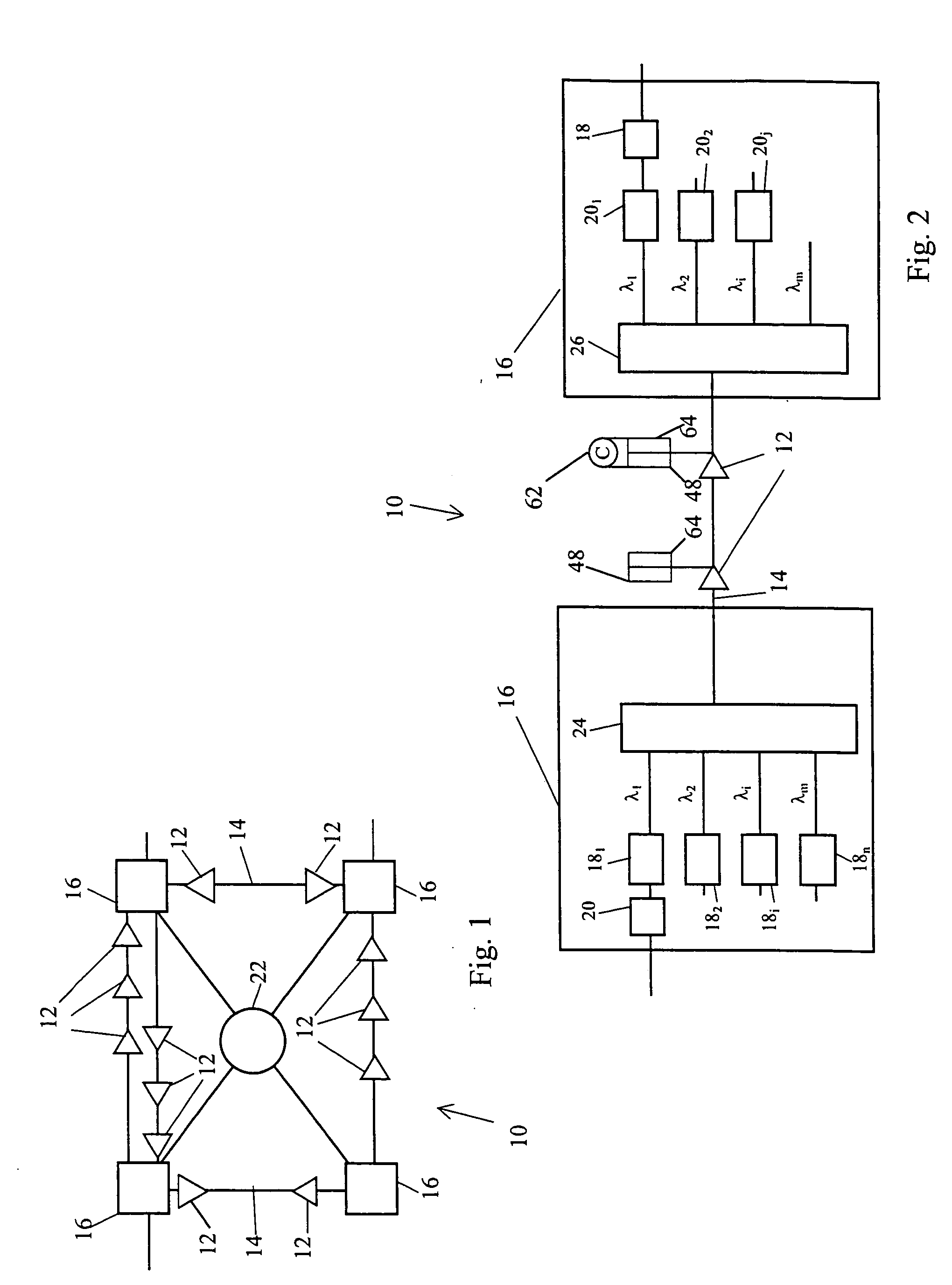
[0030] Optical systems 10 of the present invention include an optical amplifier 12 disposed along an optical transmission fiber 14 to optically amplify optical signals passing between optical processing nodes 16. One or more transmitters 18 can be included in the nodes 16 and configured to transmit information via the optical signals in one or more information carrying signal wavelengths, or signal channels, λi to one or more optical receivers 20 in other nodes 16. The optical system 10 can be configured in multi-dimensional networks controlled by a network management system 22 (FIG. 1) or in one or more serially connected point to point links (FIG. 2).

[0031] The optical processing nodes 16 may also include other optical components, such as one or more add / drop devices and optical switches / routers / cross-connects interconnecting the transmitters 18 and receivers 20. For example, broadcast and / or wavelength reusable, add / drop devices, and optical and electrical / digital cross connect ...


PUM


Abstract

Optical transmission systems of the present invention include at least one optical amplifier configured to provide optical amplification of one or more information carrying optical signal wavelengths. At least one optical amplifier is controlled based on an in situ performance characterization of the at least one optical amplifier and the transmission fiber. The in situ, or installed, performance characteristics of the optical amplifier can be characterized based on relative gain measurements over the signal wavelength range as a function of the supplied pump power. The installed characterization allows the optical amplifier performance and gain profiles to be tightly controlled over the signal wavelength range in the transmission system.

Description

CROSS-REFERENCE TO RELATED APPLICATIONS [0001] Not Applicable STATEMENT REGARDING FEDERALLY SPONSORED RESEARCH OR DEVELOPMENT [0002] Not Applicable BACKGROUND OF THE INVENTION [0003] The present invention is directed generally to optical transmission systems. More particularly, the invention is directed toward optical transmission systems including in situ characterized and calibrated optical amplifiers. [0004] Digital technology has provided electronic access to vast amounts of information. The increased access has driven demand for faster and higher capacity electronic information processing equipment (computers) and transmission networks and systems to link the processing equipment. [0005] In response to this demand, communications service providers have turned to optical communication systems, which have the capability to provide substantially larger information transmission capacities than traditional electrical communication systems. Information can be transported through opti...

Claims


Application Information

Patent Timeline
29 Sep 2005
Publication
US20050213985A1
IPC
H01S3/094; H01S3/102; H01S3/30; H04B10/00; H04B10/17
CPC
H01S3/094096; H01S3/1022; H04B10/294; H04B10/2916; H01S3/302
Inventors
STEPHENS, THOMAS D.; ZANONI, RAYMOND