Wafer carrier with pressurized membrane and retaining ring actuator

Active Publication Date: 2005-09-29
REVASUM INC +1
View PDF11 Cites 48 Cited by
  • Summary
  • Abstract
  • Description
  • Claims
  • Application Information

AI Technical Summary

Benefits of technology

[0011] The methods and devices described below provide for a wafer carrier adapted to greatly reduce the edge effect and allow a wafer to be uniformly polished across its entire surface. A wafer carrier having a pressure-regulated soft membrane behind the wafer, a retaining ring having a retaining ring actuator, and a pressurized edge c

Problems solved by technology

Using this type of carrier may not conform the front wafer surface of the wafer to the surface of the polishing pad resulting in planarization non-uniformities.
When wafer surface distortion occurs, the high spots are polished at the same time as the low spots giving some degree of uniformity but also resulting in poor planarization.
In addtion to wafer distortion, the relatively high pressure also results in excessive material removal along the edges of the silicon wafer.
When the amount of material removed is excessive, the entire wafer or portions of the wafer become unuseable.
While many soft backed wafer carrier configurations are used in CMP, their use has not been entirely satis

Method used


Image

  • Wafer carrier with pressurized membrane and retaining ring actuator
  • Wafer carrier with pressurized membrane and retaining ring actuator
  • Wafer carrier with pressurized membrane and retaining ring actuator

Examples


Example

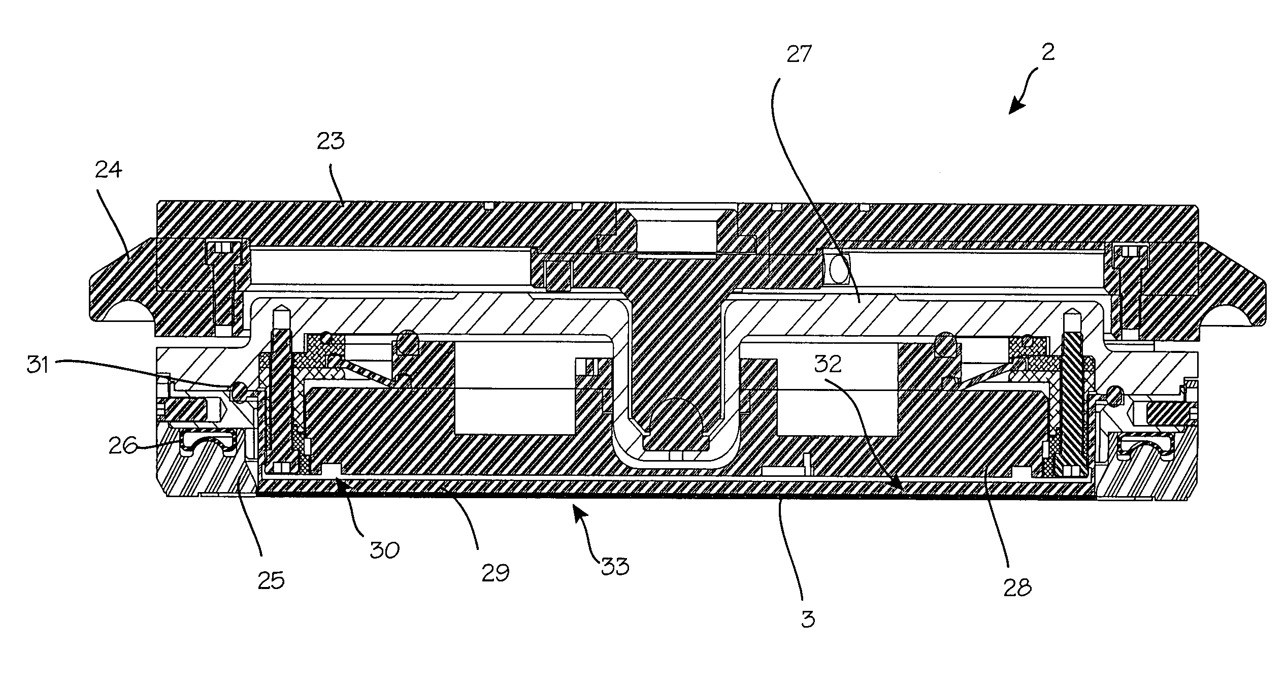
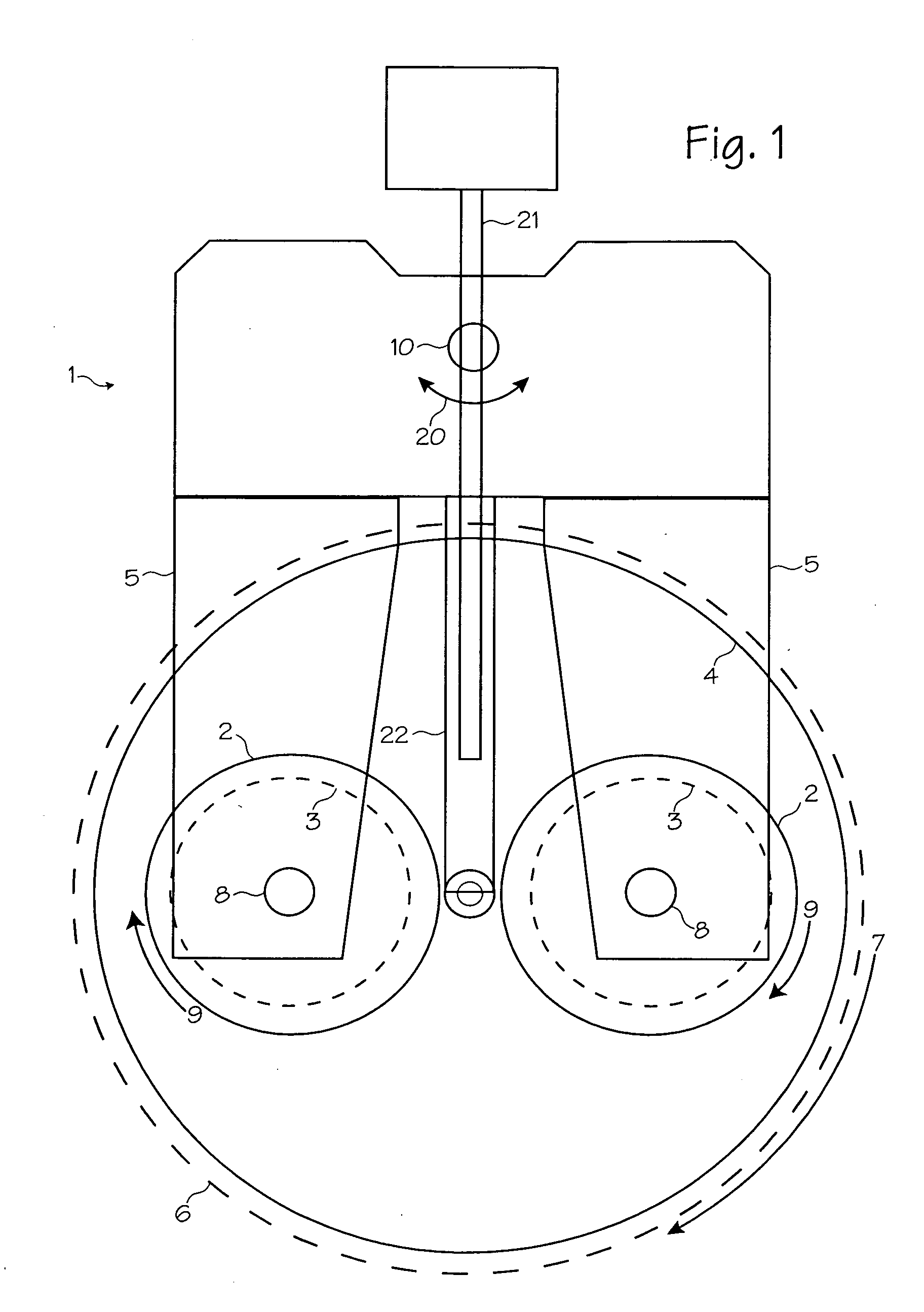
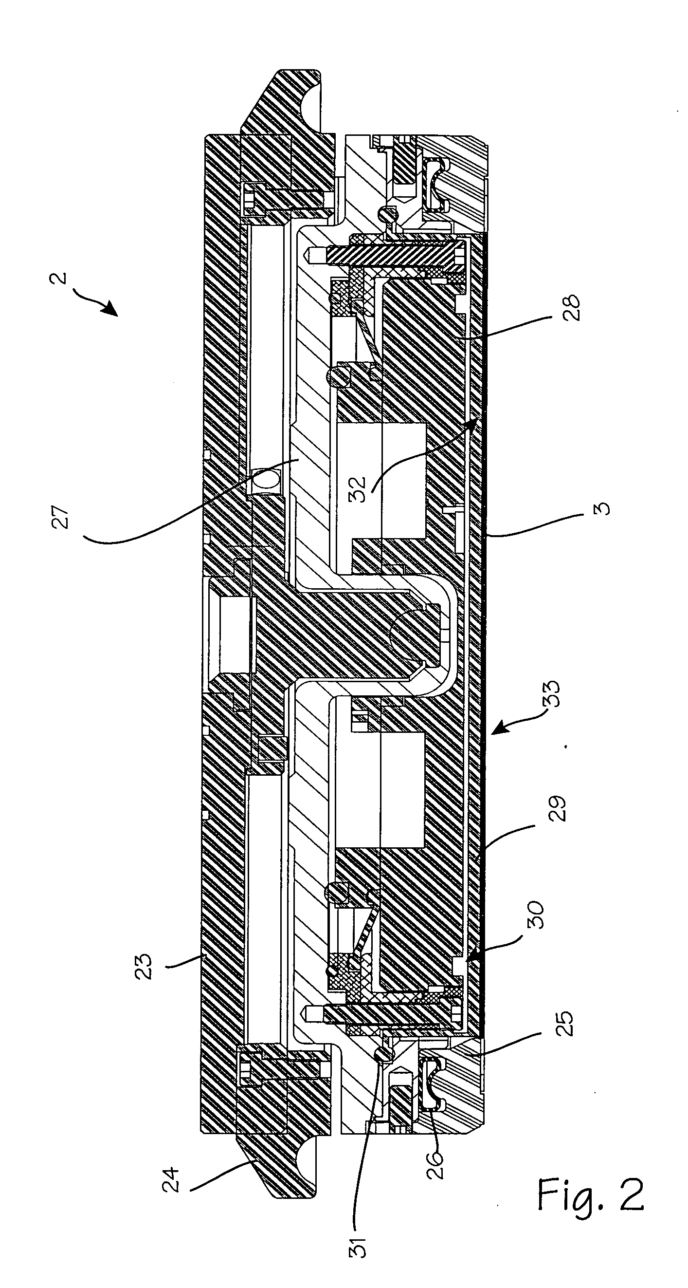
[0016]FIG. 1 shows a system 1 for performing chemical mechanical planarization (CMP). One or more polishing heads or wafer carriers 2 hold wafers 3 (shown in phantom to indicate their position underneath the wafer carrier) suspended over a polishing pad 4. A wafer carrier 2 thus has a means for securing and holding a wafer 3. The wafer carriers 2 are suspended from translation arms 5. The polishing pad is disposed on a platen 6, which spins in the direction of arrows 7. The wafer carriers 2 rotate about their respective spindles 8 in the direction of arrows 9. The wafer carriers 2 are also translated back and forth over the surface of the polishing pad by the translating spindle 10, which moves as indicated by arrows 20. The slurry used in the polishing process is injected onto the surface of the polishing pad through slurry injection tube 21, which is disposed on or through a suspension arm 22. (Other chemical mechanical planarization systems may use only one wafer carrier 2 that h...


PUM

PropertyMeasurementUnit
Forceaaaaaaaaaa
Pressureaaaaaaaaaa
Diameteraaaaaaaaaa

Abstract

A wafer carrier for controlling downward force and edge effect during chemical mechanical planarization. A retaining ring actuator is disposed within the retaining ring to control the height of the retaining ring relative to the bottom surface of the wafer carrier. An inflatable membrane is disposed across the bottom surface of the wafer carrier such that pressure in the bladder is independently regulated to control the downward force acting on the wafer during CMP. In addition, an edge control bladder may also be disposed within the carrier such that if the pressure in the bladder is also regulated, the amount of force on the edge of the wafer changes. By regulating retaining ring actuator pressure, inflatable membrane pressure, and edge control bladder pressure, non-uniformities in the wafer surface and edge effect may be addressed during CMP.

Description

[0001] This application claims priority to U.S. Provisional Application 60 / 550,806, filed Mar. 5, 2004FIELD OF THE INVENTIONS [0002] The inventions described below relate the field of wafer carriers and particularly to wafer carriers used during chemical mechanical planarization of silicon wafers. BACKGROUND OF THE INVENTIONS [0003] Integrated circuits, including computer chips, are manufactured by building up layers of circuits on the front side of silicon wafers. An extremely high degree of wafer flatness and layer flatness is required during the manufacturing process. Chemical-mechanical planarization (CMP) is a process used during device manufacturing to flatten wafers and the layers built-up on wafers to the necessary degree of flatness. [0004] Chemical-mechanical planarization is a process involving polishing of a wafer with a polishing pad combined with the chemical and physical action of a slurry pumped onto the pad. The wafer is held by a wafer carrier, with the backside of...

Claims


Application Information

Patent Timeline
IPC IPC(8): B24B1/00B24B37/04B24B41/06
CPCB24B37/30B24B41/007B24B37/32
Inventor FUHRIMAN, JOHNWELLS, CARLTONKALENIAN, BILLSPIEGEL, LARRY
Owner REVASUM INC
Why Eureka
Try Eureka