Endoscope system having multiaxial-mode laser-light source or substantially producing multiaxial-mode laser light from single-axial-mode laser light

a laser light source and endoscope technology, applied in the field of endoscope systems, can solve problems such as uneven normal image, and achieve the effect of suppressing uneven diagnostic imag

Inactive Publication Date: 2005-09-29
FUJIFILM CORP
View PDF26 Cites 13 Cited by
  • Summary
  • Abstract
  • Description
  • Claims
  • Application Information

AI Technical Summary

Benefits of technology

[0014] An object of the present invention is to provide an endoscope system which uses a laser-light source as a source of illumination light or excitation light, and suppresses unevenness in a diagnostic image.

Problems solved by technology

The interference of the illumination light causes unevenness in the normal image.

Method used


Image

  • Endoscope system having multiaxial-mode laser-light source or substantially producing multiaxial-mode laser light from single-axial-mode laser light
  • Endoscope system having multiaxial-mode laser-light source or substantially producing multiaxial-mode laser light from single-axial-mode laser light
  • Endoscope system having multiaxial-mode laser-light source or substantially producing multiaxial-mode laser light from single-axial-mode laser light

Examples


first embodiment

Operation of First Embodiment

[0073] The operations of the fluorescence endoscope system as the first embodiment of the present invention are explained below for the case where a synthesized image is displayed by using digitized data of autofluorescence images in two different wavelength bands and a reflection image.

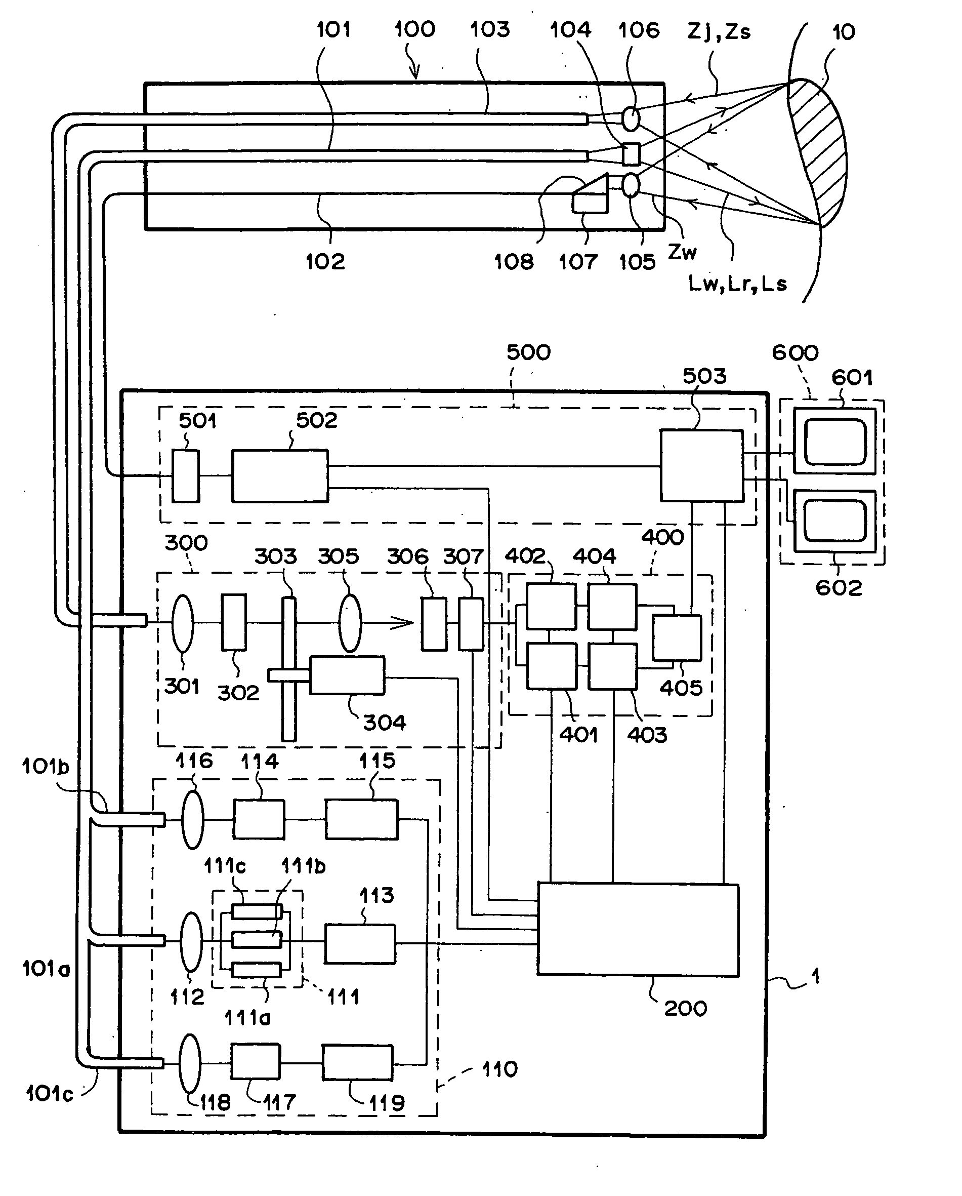
[0074] First, in order to obtain the autofluorescence images in the two different wavelength bands, the computer 200 activates the power supply 115 by sending a control signal to the power supply 115. Then, the GaN semiconductor laser element 114 emits multiaxial-mode excitation light Lr having a center wavelength of 410 nm. The excitation light Lr is collected by the condenser lens 116, and enters the excitation-light guide 101b. The excitation light Lr is guided through the excitation-light guide 101b to the front end of the endoscope insertion unit 100, and is then applied to the living tissue 10 through the illumination lens 104.

[0075] When the living tissue 10 is i...

second embodiment

[0085] The second embodiment of the present invention is explained below. FIG. 4 is a diagram illustrating an outline of a construction of the fluorescence endoscope system as the second embodiment of the present invention. In FIG. 4, elements having the same reference numbers as FIG. 1 have the same functions as the corresponding elements in FIG. 1, and explanations of the functions of the common elements are not repeated below. The fluorescence endoscope system of FIG. 4 realizes the functions of both the second and sixth aspects of the present invention. The fluorescence endoscope system of FIG. 4 is different from the fluorescence endoscope system of FIG. 1 in the light sources of the white light Lw and the excitation light Lr. That is, the fluorescence endoscope system of FIG. 4 comprises an illumination unit 120 instead of the illumination unit 110.

[0086] The illumination unit 120 comprises a white-light source 128 instead of the white-light source 111, and an excitation-ligh...

third embodiment

[0091] The third embodiment of the present invention is explained below. FIG. 6 is a diagram illustrating an outline of a construction of the fluorescence endoscope system as the third embodiment of the present invention. In FIG. 6, elements having the same reference numbers as FIG. 1 have the same functions as the corresponding elements in FIG. 1, and explanations of the functions of the common elements are not repeated below. The fluorescence endoscope system of FIG. 6 realizes the functions of both the third and seventh aspects of the present invention.

[0092] The fluorescence endoscope system of FIG. 6 is different from the fluorescence endoscope system of FIG. 1 in that a vibrator (or shaker) 135 is attached to the white-light guide 111a, a vibrator (or shaker) 132 is attached to the excitation-light guide 101b, and controllers 136 and 133 for the vibrators 135 and 132 are provided. In addition, the fluorescence endoscope system of FIG. 6 comprises a white-light source 131 inst...


PUM


Abstract

In an endoscope system including: a light emission unit emits laser light as illumination light or excitation light; a light guide unit guides the illumination light or the excitation light to an object; and an image pickup unit picks up a normal image formed with reflection light generated by reflection of the illumination light from the object or a fluorescence image emitted from the object in response to the excitation light. The laser light is multiaxial-mode laser light, or the light emission unit includes a plurality of laser-light sources which emit single-axial-mode laser beams having different wavelengths or phases. Alternatively, a vibration unit which vibrates the light guide unit is provided, or a high-frequency signal is superimposed on a driving current of the light emission unit, so that the wavelength of the laser light is shifted among a plurality of values.

Description

BACKGROUND OF THE INVENTION [0001] 1. Field of the Invention [0002] The present invention relates to an endoscope system which illuminates living tissue with illumination light or excitation light, detects reflection of the illumination light from the living tissue or fluorescence light emitted from the living tissue in response to the illumination of the excitation light, and displays an image indicating information on the living tissue. [0003] 2. Description of the Related Art [0004] Endoscopes have been widely used for observing internal parts of living bodies, and treating diseased areas of the living bodies while observing the diseased areas. Recently, the following techniques have been proposed for the endoscope systems: [0005] (a) Techniques of illuminating living tissue with illumination light, picking up a normal image formed with reflection light from the living tissue, and displaying the normal image [0006] (b) Techniques of illuminating living tissue with excitation ligh...

Claims


Application Information

Patent Timeline
Patent Type & Authority Applications(United States)
IPC IPC(8): G02B23/26A61B1/00A61B1/04A61B1/06A61B5/00H01S5/323
CPCA61B1/00186A61B1/043A61B5/0084A61B5/0071A61B1/0638
Inventor HAKAMATA, KAZUO
Owner FUJIFILM CORP
Why Eureka
Try Eureka