Universal support arm and tracking array

a technology of universal support and tracking array, applied in the field of computer assisted navigation, can solve the problems of unsuitable surgical instruments so equipped, difficult to accurately define the position of instruments, and difficult to accurately determine the geometry of the combination

Inactive Publication Date: 2005-09-29
ZIMMER TECH INC
View PDF52 Cites 118 Cited by
  • Summary
  • Abstract
  • Description
  • Claims
  • Application Information

AI Technical Summary

Benefits of technology

[0013] The present invention provides a universal tracking apparatus for a surgical instrument, the tracking apparatus including a support arm and tracking array. The support arm allows position adjustment of the tracking array between a number of predefined orientations relative to the instrument which are recognizeable and registerable in the navigation system. The support arm may be coupled with multiple types of surgical instruments and used to accurately define the position of the instrument in an anatomical model generated by the navigation system. The adjustable coupling between the tracking array and the support arm allows the surgeon to determine which orientation is best suited for the surgical application and also allows the surgeon to adjust the position of the tracking array during a surgical procedure without the need to re-register the tracking apparatus. The tracking array may also include at least one repositionable reference element to allow a single tracking array to be configured for use with a plurality of different instruments, wherein differing geometries defined by the tracking array and corresponding to particular instruments are recognizable and registerable by the navigation system.
[0015] The third member includes a mounting interface for coupling a tracking array which may be registered in the computer-assisted navigation system. By repositioning the second and third members to selected predefined positions, the position of the tracking array relative to the instrument may be adjusted. Also, at least one of the first, second, and third members may include a reference indicator registerable in the navigation system, such that after the tracking apparatus is adjusted, the orientation of the tracking apparatus may be automatically recognized by the navigation system, eliminating the need for the surgeon to manually re-register the tracking apparatus in the navigation system.
[0016] In one exemplary embodiment, the first and / or third members may be coupled to the second member so that they may be rotated to a limited number of predefined positions relative to the second member, thereby simplifying the task of indicating to the computer-assisted navigation system the relative geometry between the instrument and the tracking array. For example, a set of matching protuberances and recesses may be located on adjacent members and the members biased by a spring to engage the protuberances in the recesses. To reposition the first or third member relative to the second member, the members may be pulled slightly apart against the force of a spring to disengage the protuberances from the recesses and then rotated to another predefined position in which the protuberances may again engage matching recesses. The selected predefined position may then be input manually to the computer-assisted navigation system, or a reference element may be coupled to the first member in order for the computer-assisted navigation system to determine the geometry between the tracking array and first member, thereby defining the geometry between the tracking array and instrument.
[0019] The adjustable or repositionable reference element may be repositioned by providing, for example, multiple mounting interfaces to which the reference element may be coupled, or by providing a translating, pivoting, or otherwise movable mounting interface which is coupled to the body of the tracking array and upon which the reference element is mounted. The mechanism for moving the mounting interface relative to the body may include detents or other mechanical devices to provide predetermined positions. Optionally, a template may be used for accurately repositioning the movable reference element relative to the other reference elements. The template may include recesses corresponding to the fixed reference elements and the multiple positions of the movable reference element.
[0020] Advantageously, the support arm or tracking array may be repositioned to provide an optimal view of the tracking array by the position sensor, or to provide unobstructed access for the surgeon to the anatomical structures of the patient without having to uncouple the support arm from the instrument or having to re-register the tracking apparatus.
[0021] Further, once an instrument is positioned and secured relative to the anatomical structures of the patient, the support arm and tracking array may be detached from a surgical instrument, providing increased access to the instrument and anatomical structure. Additionally, the flexibility of adjusting the pivotable couplings of the support arm and the movable reference element of the tracking array reduces the number of different components that need be available to perform a surgical procedure.

Problems solved by technology

The variability associated with arbitrarily clamping a tracking array to a surgical instrument, as well as the possibility of a clamped tracking array slipping relative to the surgical instrument, causes uncertainty in the geometry of the combination, thus requiring careful and possibly repeated instrument calibrations.
However, a surgical instrument so equipped may not be suitable for procedures which require the array to be in a different position relative to the instrument, or may not be suitable for use without the computer-assisted navigation system because of the permanently-affixed tracking array.
For example, the position of the tracking array may present a barrier to accessing the anatomical structures visually or with other instruments, or the position of the tracking array may need to be adjusted to place the tracking array properly in the “line of sight” of, or otherwise within the applicable field of detection of, the computer-assisted navigation system.
Disadvantageously, such a system requires a supply of many different tracking arrays for each surgical procedure.

Method used


Image

  • Universal support arm and tracking array
  • Universal support arm and tracking array
  • Universal support arm and tracking array

Examples


Embodiment Construction

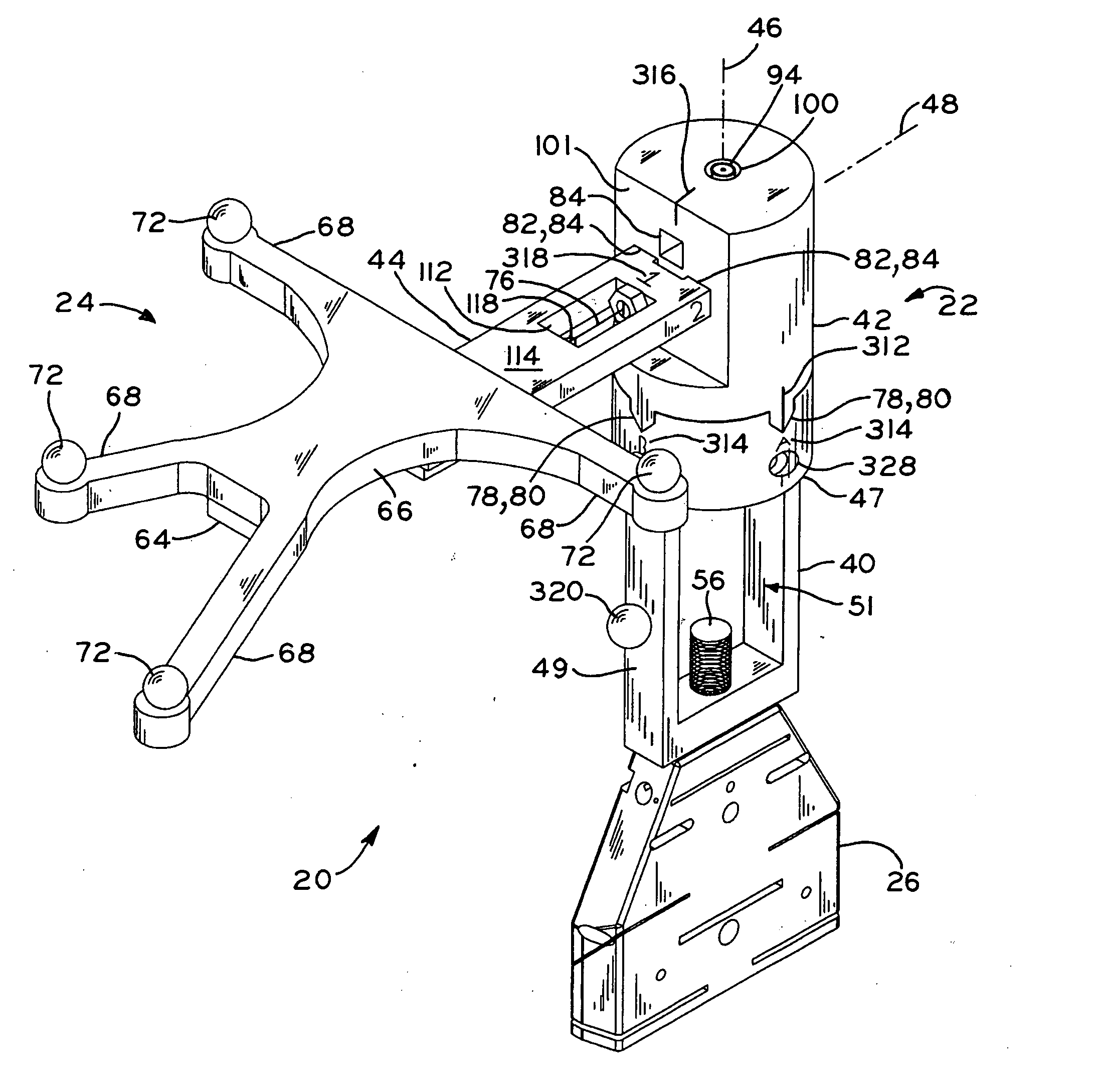
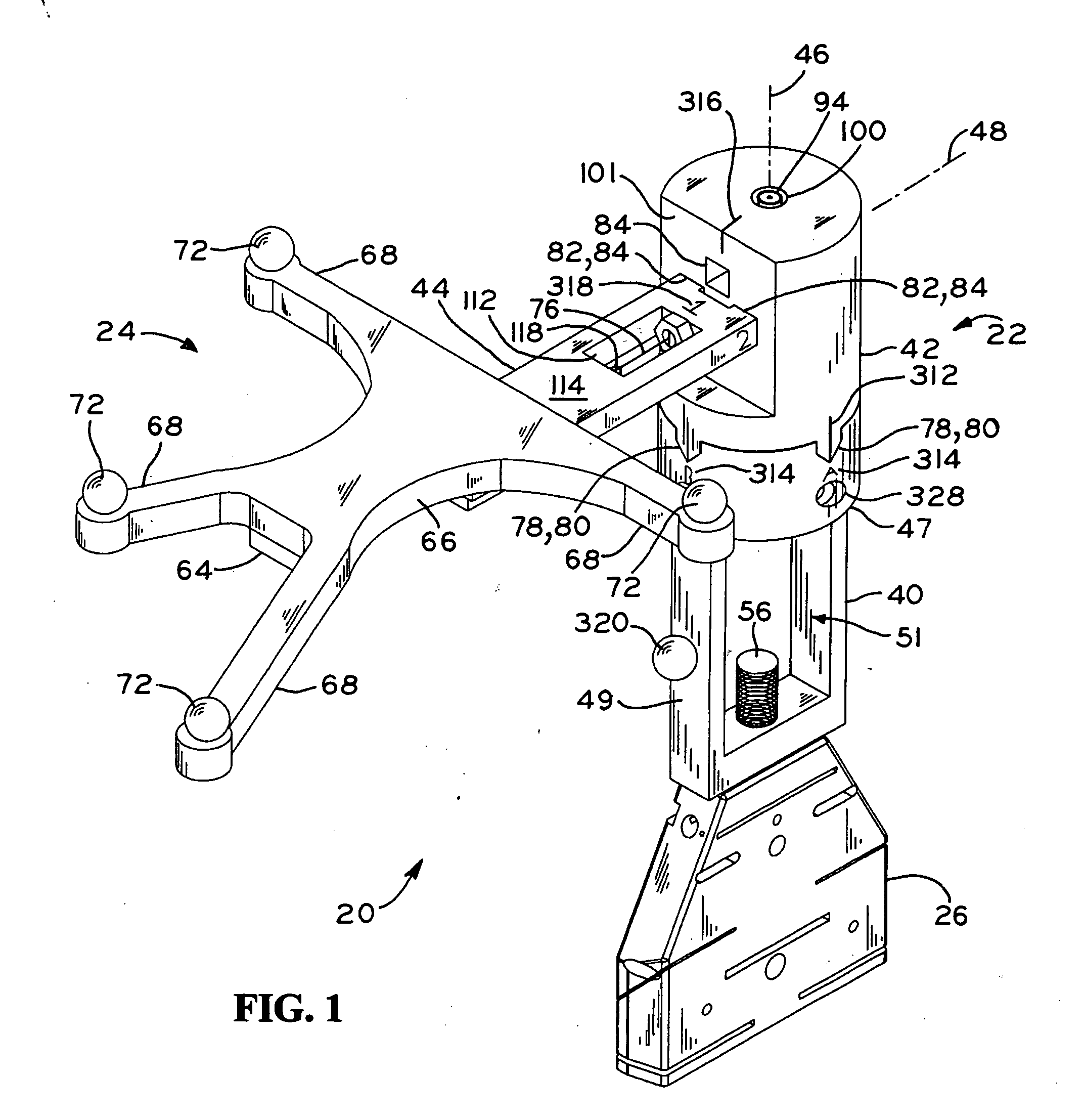
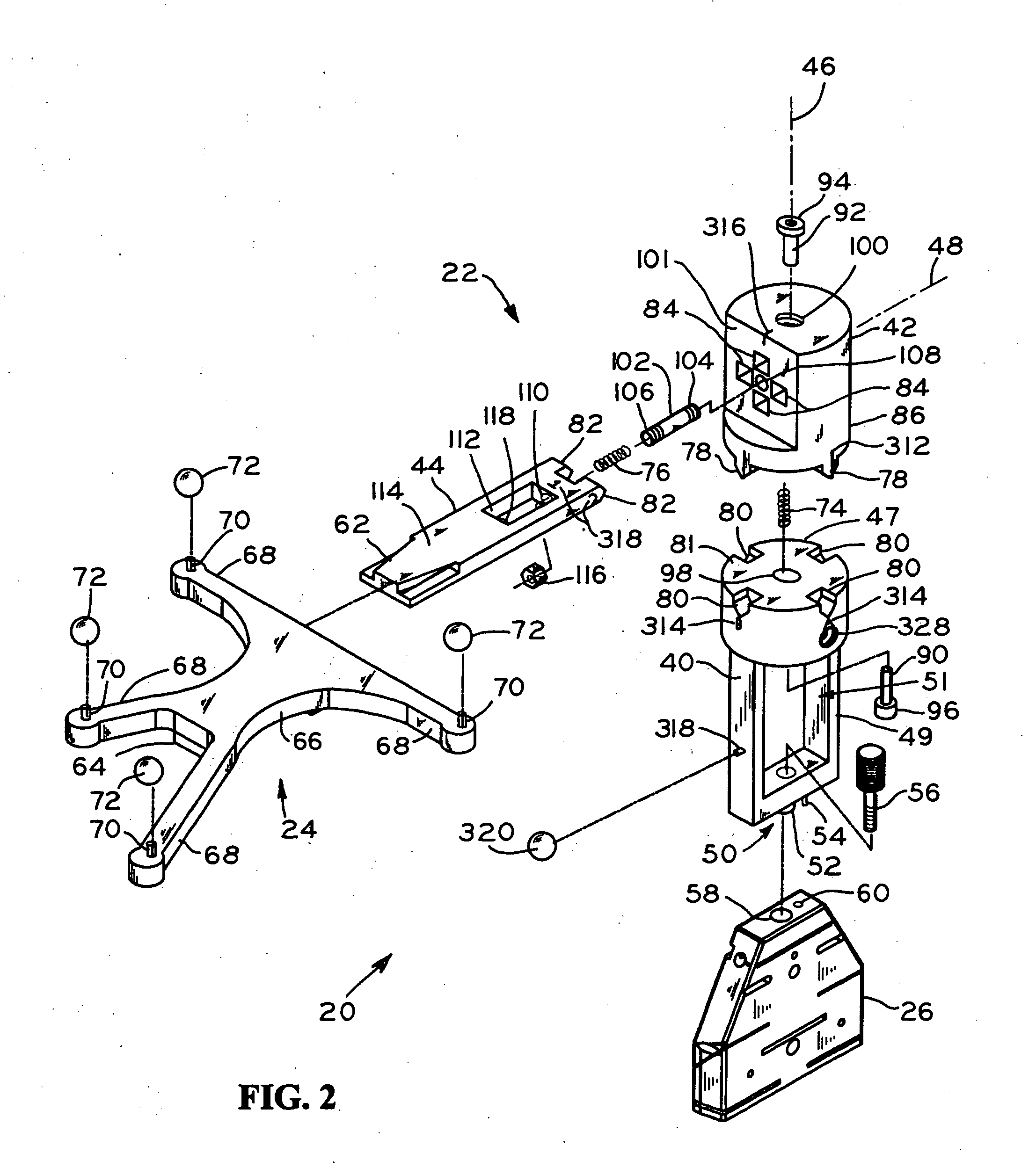
[0044] Referring initially to FIG. 1, an exemplary tracking apparatus 20 according to the present invention includes support arm 22 for coupling tracking array 24 to surgical instrument 26. Support arm 22 displaces tracking array 24 from instrument 26, for example for placing array 24 within the field of view or detection of position sensing unit 28 of computer-assisted navigation system 30, shown in FIG. 3. Additionally, support arm 22 allows positional adjustment of tracking array 24 relative to instrument 26, thereby providing adjustment of the geometry between instrument 26 and array 24. Instrument 26 may be any instrument used with navigation system 30, for example a cut guide for orthopedic implant surgery, or a saw, reamer, drill, or other surgical instrument.

[0045] Referring to FIG. 3, operating room arrangement 32 includes computer-assisted navigation system 30, position sensing unit 28 for detecting the position of tracking array 24 of tracking apparatus 20, and patient 3...


PUM


Abstract

A universal tracking apparatus for a surgical instrument, the tracking apparatus including a support arm and tracking array. The support arm allows position adjustment of the tracking array between a number of predefined orientations relative to the instrument which are recognizeable and registerable in the navigation system. The support arm may be coupled with multiple types of surgical instruments and used to accurately define the position of the instrument in an anatomical model generated by the navigation system. The adjustable coupling between the tracking array and the support arm allows the surgeon to determine which orientation is best suited for the surgical application and also allows the surgeon to adjust the position of the tracking array during a surgical procedure without the need to re-register the tracking apparatus. The tracking array may also include at least one repositionable reference element to allow a single tracking array to be configured for use with a plurality of different instruments, wherein differing geometries defined by the tracking array and corresponding to particular instruments are recognizable and registerable by the navigation system.

Description

CROSS REFERENCE TO RELATED APPLICATIONS [0001] This application is related to and claims the benefit under Title 35, U.S.C. §119(e) of U.S. Provisional Patent Application Ser. No. 60 / 550,460, entitled UNIVERSAL SUPPORT ARM AND TRACKING ARRAY, filed on Mar. 5, 2004.BACKGROUND OF THE INVENTION [0002] 1. Field of the Invention [0003] The present invention relates to computer-assisted navigation for use in surgical procedures and, more specifically, to a tracking apparatus including a support arm which may be detachably coupled to a surgical instrument, the support arm including a tracking array for use in accurately locating the position of the surgical instrument during a surgical procedure. [0004] 2. Description of the Related Art [0005] Various methods and guide instruments have been developed to facilitate the proper positioning of a surgical instrument during a surgical procedure. Such instruments and methods include the use of mechanical surgical guides which can be positioned in...

Claims


Application Information

Patent Timeline
Patent Type & Authority Applications(United States)
IPC IPC(8): A61B5/05A61B17/00A61B17/15A61B17/90A61B19/00
CPCA61B17/154A61B19/44A61B2019/5483A61B2017/00477A61B19/54A61B90/39A61B90/90A61B2090/3983
Inventor GRIMM, JAMES E.MCGINLEY, SHAWN E.WILSON, JACQUE R.HALL, MALEATA Y.WALRIVEN, DALE E.HUI, SUDIPRANGAIAH, CHETAN
Owner ZIMMER TECH INC
Why Eureka
Try Eureka