Generators, transformers and stators containing high-strength, laminated, carbon-fiber windings

a technology of carbon fiber windings and generators, which is applied in the direction of transformers/inductance coils/windings/connections, transformers, dynamo-electric machines, etc., can solve the problems of rotor degradation, limited life of generators, and failure to meet the requirements so as to reduce repair, the effect of reducing the number of times of maintenan

Inactive Publication Date: 2005-10-06
WNOROWSKI EDWARD J JR +1
View PDF20 Cites 27 Cited by
  • Summary
  • Abstract
  • Description
  • Claims
  • Application Information

AI Technical Summary

Benefits of technology

[0012] The carbon fiber windings provide the apparatus with increased resistance to high temperature, high humidity and / or mechanical force, as compared to conventional metal materials such as copper or aluminum. The apparatus may further comprise terminals for directing flow and electrical connections for transmitting electrical energy that both may contain electrically conductive carbon fibers of the invention, and one or more cooling fans or heat exchangers for reducing the temperature of said apparatus. Preferred apparatus of the invention include generators and large capacity generator for the production of electrical energy.

Problems solved by technology

Generators have a limited life and must be repaired, reconstructed or replaced periodically.
Degradation of the rotor can be caused by a number of factors, including a breakdown in insulation due to humidity, temperature and mechanical wear.
This degradation can lead to shorted turns, a field ground, or an in-service operational incident that can require premature maintenance work.
However, this process is both expensive and time consuming.

Method used


Image

  • Generators, transformers and stators containing high-strength, laminated, carbon-fiber windings
  • Generators, transformers and stators containing high-strength, laminated, carbon-fiber windings
  • Generators, transformers and stators containing high-strength, laminated, carbon-fiber windings

Examples


example a

Investigation into the Variation of Power Factor Versus Excitation

[0043] To investigate the effects of varying the excitation field on the power factor of the generator current at various mechanical loads.

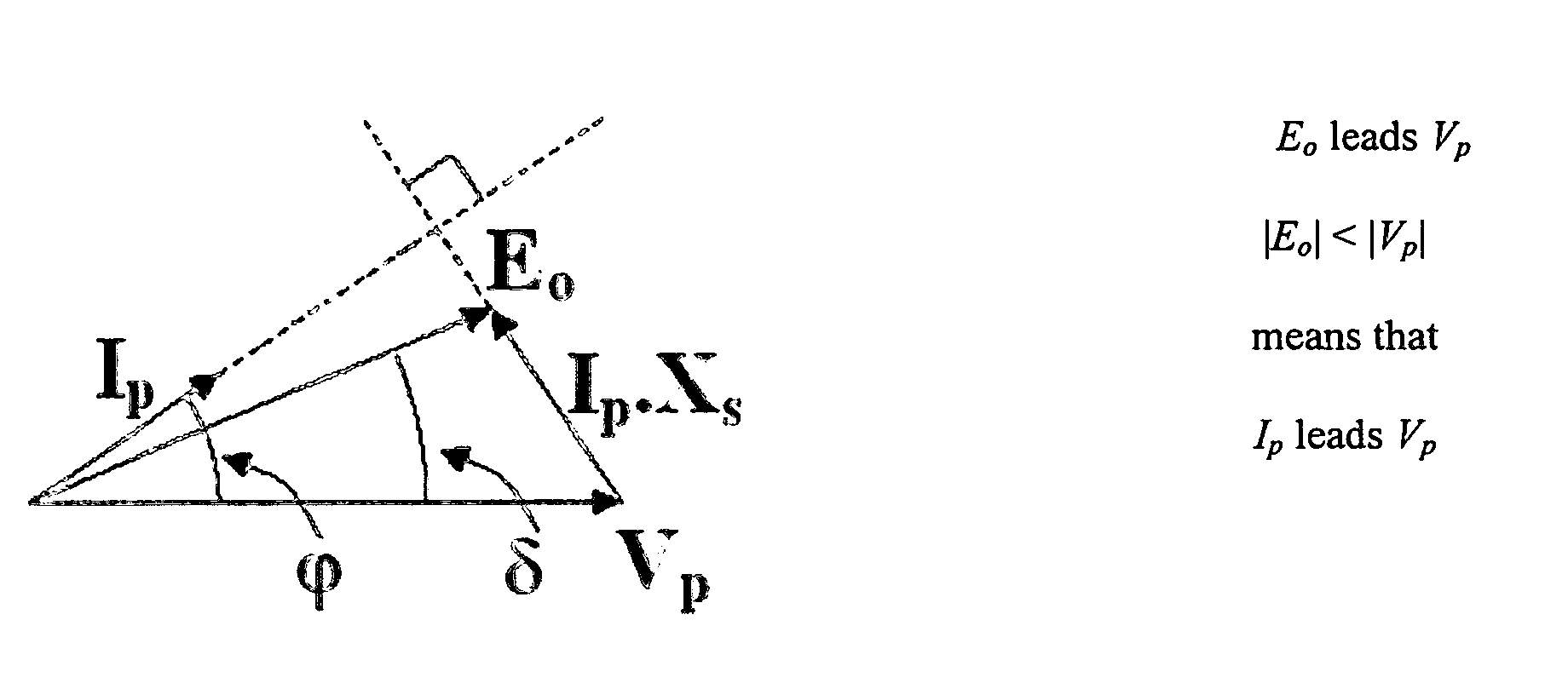
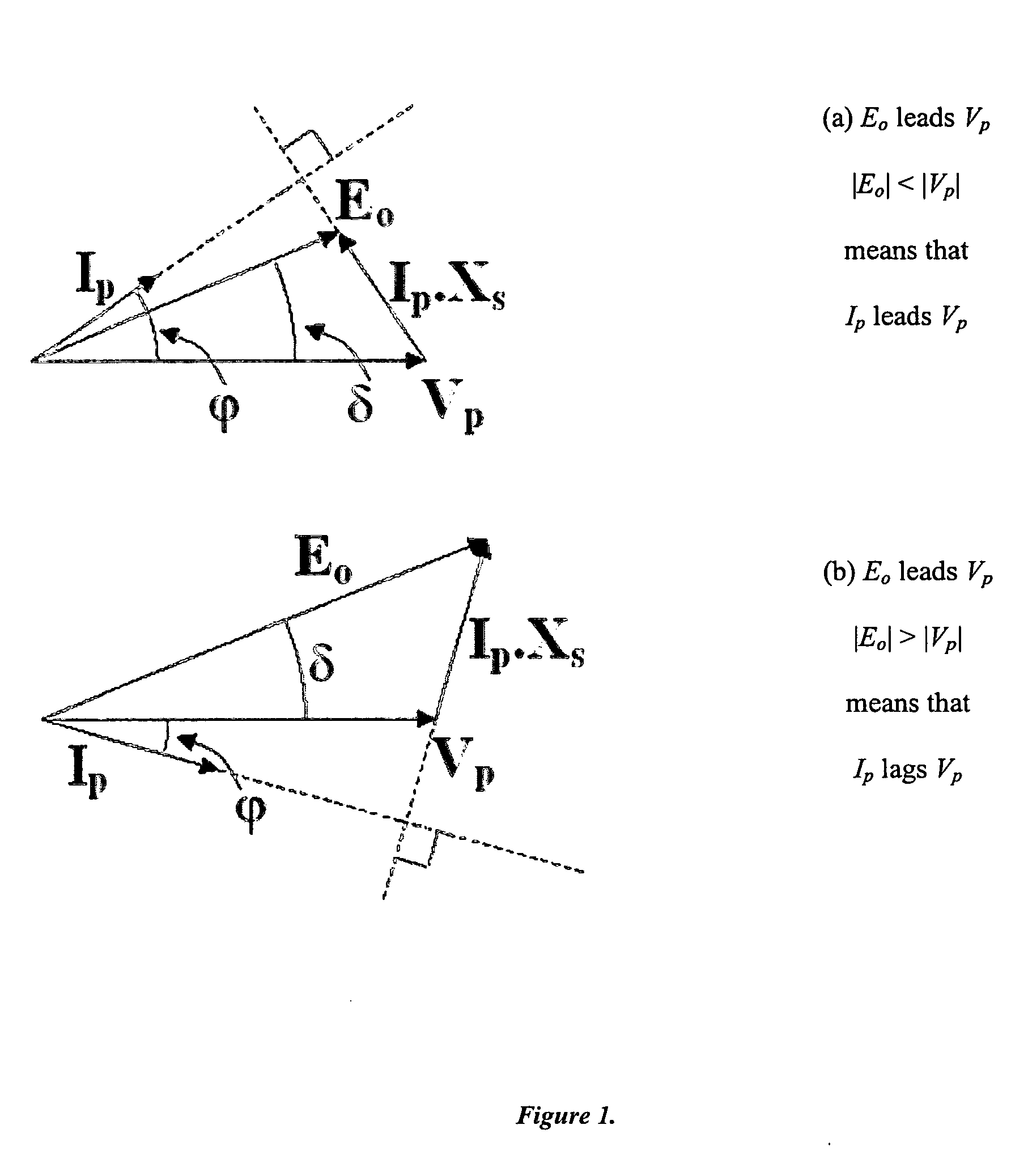
[0044] A synchronous generator is loaded by applying mechanical torque to the shaft that causes the induced e.m.f. to lead the terminal voltage. The difference between Eo and Vp is dropped across the synchronous reactance and causes a phase current to flow. Notice that the resultant current may not only change in magnitude but can also change phase, thus influencing the power factor. Not only can the phase of the e.m.f. be controlled, but the magnitude of the e.m.f. may also be adjusted. Excitation Voltage and Current.

[0045] From the phasor diagrams it can be seen that the power factor of the synchronous generator may be varied by increasing or decreasing the excitation. To draw the phasor diagram the following procedure may be used: [0046] 1. A line proportional to the phase te...

example b

Investigation into the Torque / Load Angle Characteristic with Excitation and Hence Stability

[0056] To investigate the effects of excitation on the torque versus load angle characteristic and to determine the limit of stability.

[0057] The equation for the total input (shaft) power for a synchronous machine is given by: Wshaft=3⁢Vp⁢EoXs⁢sin⁢ ⁢δ(1)

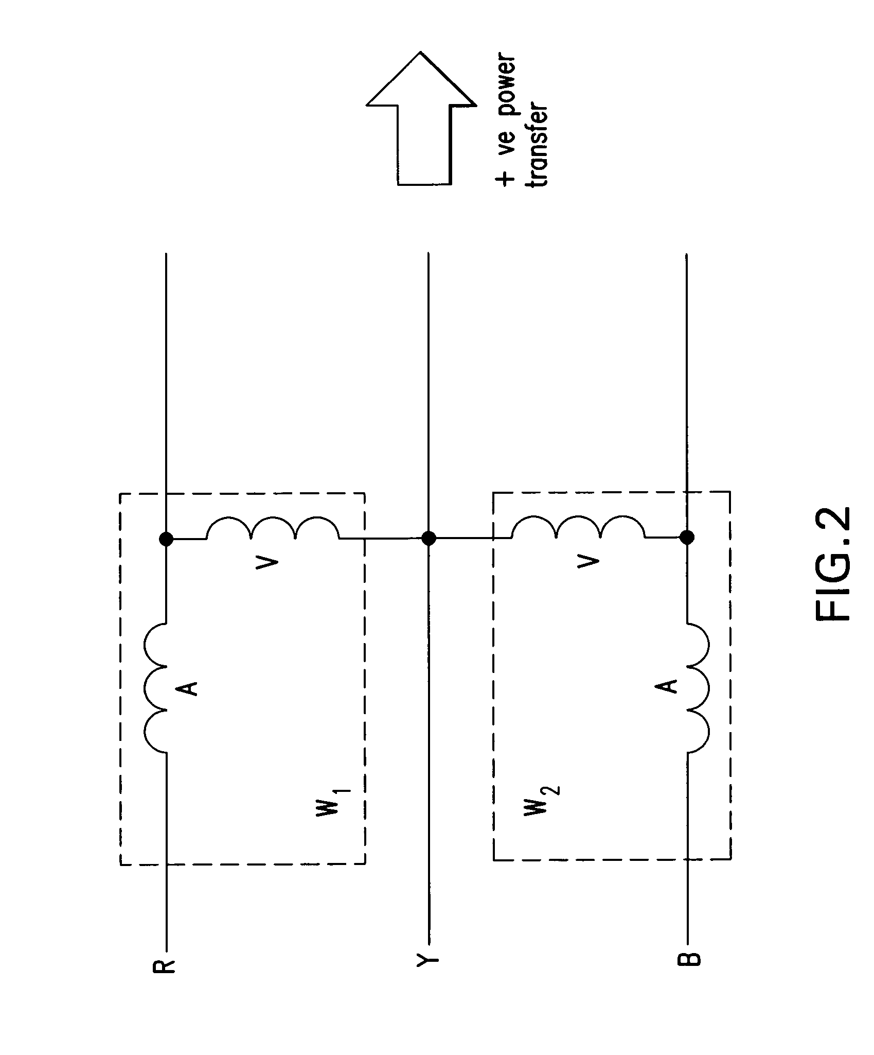
[0058] To find information on the torque versus load angle characteristic for synchronous machines one needs to ascertain how this is influenced by the magnitude of the excitation field. One can also determine what is meant by “stability”, why it is important, and the difference between “static” and “transient” stability. Further, one can determine how to connect the circuit and assess the permissible ranges of all of the quantities to measure.

[0059] Results are linked back to the theory and previous experiments. Types of stability are determined during this test and how the test is influenced by disturbances. Generators on-load can be dis...


PUM

PropertyMeasurementUnit
densityaaaaaaaaaa
thicknessaaaaaaaaaa
thicknessaaaaaaaaaa

Abstract

This invention is directed to motors, rotors and stators, transformers, generators and related apparatus comprising carbon fiber windings, and in particular, laminated carbon fiber windings for the generation of electrical energy. The invention is also directed to methods for generating electrical energy from devices of the invention and to methods for reconditioning and repairing conventional apparatus with carbon fiber windings.

Description

REFERENCE TO RELATED APPLICATIONS [0001] This invention claims priority to U.S. Provisional Application No. 60 / 553,957 of the same title and filed Mar. 18, 2004, the entirety of which is hereby incorporated by reference.BACKGROUND [0002] 1. Field of the Invention [0003] This invention is directed to motors, stators and rotors, transformers, generators, electrical connections and related apparatus comprising carbon fiber windings, and in particular, laminated carbon fiber windings for the generation of electrical energy. The invention is also directed to methods for generating electrical energy from devices of the invention and to methods for reconditioning and repairing conventional apparatus with carbon fiber windings. [0004] 2. Description of the Background [0005] Electrical generators are used around the world for all applications that require energy and especially the generation of electrical energy. Accordingly generators can be found in many shapes and sizes for use in or as p...

Claims


Application Information

Patent Timeline
Patent Type & Authority Applications(United States)
IPC IPC(8): H01F27/28H01F27/32H02K3/00H02K3/02H02K15/00
CPCH01F27/28H02K15/0006H02K3/02H01F27/32
Inventor WNOROWSKI, EDWARD J. JR.DARLING, CHARLES M. IV
Owner WNOROWSKI EDWARD J JR
Why Eureka
Try Eureka