Architecture for bidirectional serializers and deserializer

Inactive Publication Date: 2005-10-06
SEMICON COMPONENTS IND LLC
View PDF18 Cites 13 Cited by
  • Summary
  • Abstract
  • Description
  • Claims
  • Application Information

AI Technical Summary

Benefits of technology

[0015] In preferred embodiments, a REF clock is used to lock the PLL's, a WORD clock latches data into buffer registers. The data lines are bidirectional as is the bit clock line. In preferred embodiment, there is an overall master or controller that handles the data and clock direction reversals so that information is not lost. In other preferred embodiment, the synchronization between the sender and the receiver to turn around the data/clock signal directions can be handled by control/status line or lines between the two. Protocols may be developed by those skilled in the art to ensure that proper control of the communications between the sending and receiving systems. For example,

Problems solved by technology

Information being transferred would typically have error check system, so that if there was contention remain

Method used


Image

  • Architecture for bidirectional serializers and deserializer
  • Architecture for bidirectional serializers and deserializer
  • Architecture for bidirectional serializers and deserializer

Examples


Embodiment Construction

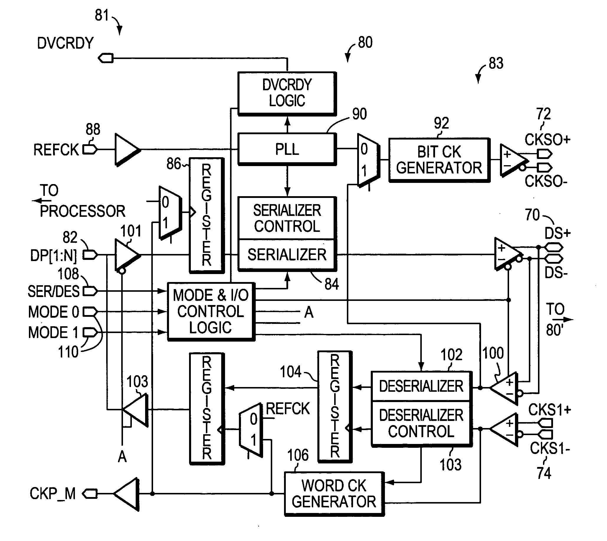
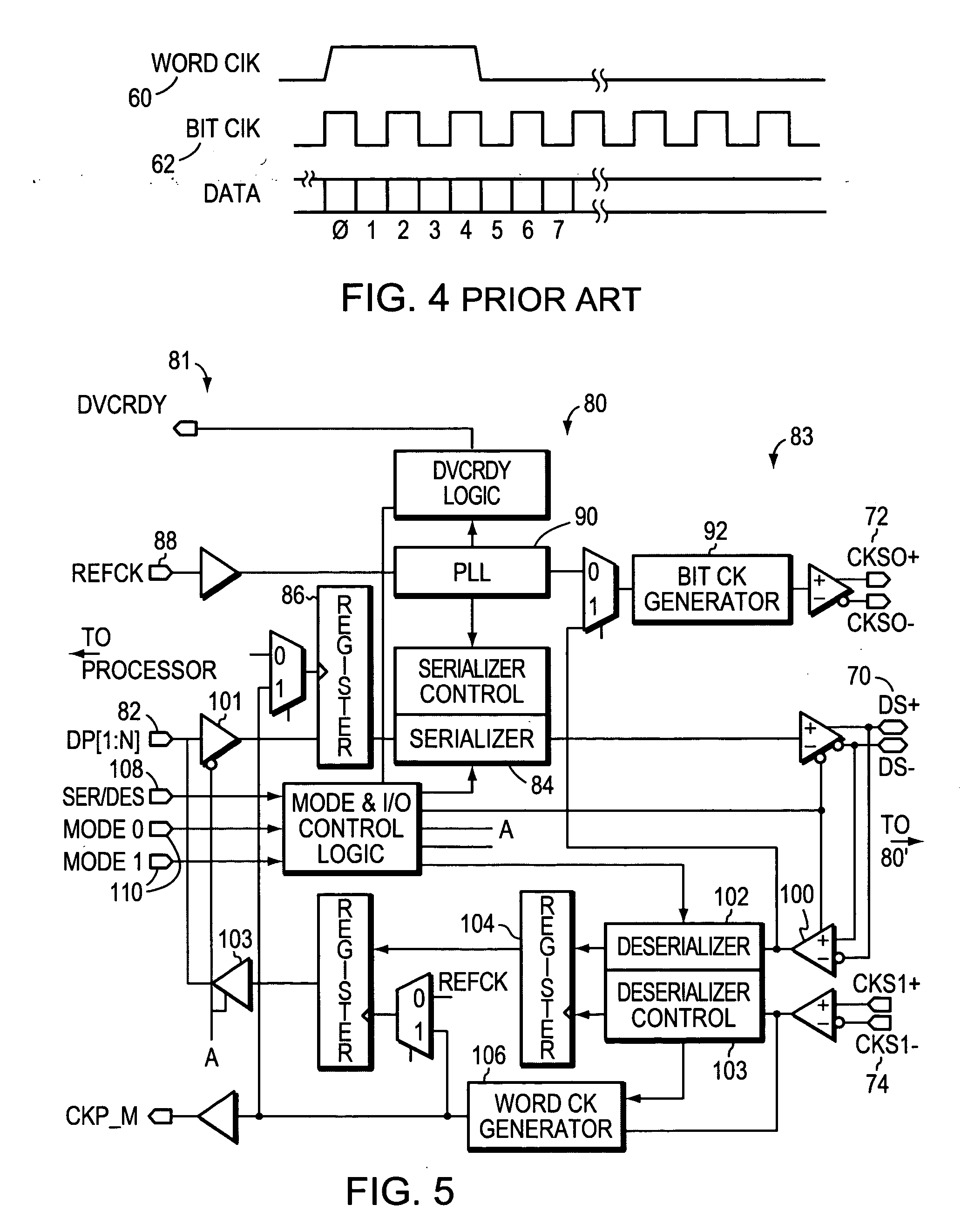
[0033]FIG. 5 is a block diagram that indicates the operation at a high, functional level showing a serializer / de-serializer 80. The left side 81 of FIG. 5 show electrical contact points arranged to be connected to a processor or computer bus system while the rights side 83 of FIG. 5 is arranged to connect to a transmission cable, or the like, that connects to corresponding pins on serializer / desrializer 80′ that is similar to the serializer / de-serializer 80. The data lines (DS+, DS−) 70, the clock out lines (CKSO+, CKSO−) 72 and the clock in lines (CKS1+, CKS1−) 74 are typically differential pairs as shown. Line drivers and receivers for differential pairs are well known in the art. Moreover, in particular applications the clock in and clock out lines may be joined together so that only a single data pair and a single clock pair are output to connect to another serializer / de-serializer 80.′ These differential pairs will be referred to as CKSO, CKS1, and DS unless a specific referenc...


PUM


Abstract

A bi-directional serializer/deserializer is disclosed using a single bi-directional data line and a single bi-directional clock line. Gated buffers are controlled to operate either sending or receiving data, and a phase locked loop provides a clock to shift data out from a shift register. A reference clock is supplied to the PLL and the PLL generates a synchronous bit clock. The bit clock is sent over the clock line in parallel with the serial data bits, and the PLL bit clock is synchronized to the data bits. The receiving system will use the bit clock to serial load a receiving shift register. When a word is received a word clock is available to inform the receiving system. An embodiment of the system sends data to a receiving system using a clock generated at the sending system. Another embodiment receives data but uses a clock that is sent from the receiving system to the sending system, wherein the sending system uses the received clock to generate a clock to send the data and a synchronous clock that is sent back to the receiving system to load the data from the data line.

Description

CROSS REFERENCE TO RELATED APPLICATIONS [0001] The present application is related to a co-filed application having the owners, the application entitled, BIT CLOCK WITH EMBEDDED WORD BOUNDARY. This application is hereby incorporated herein by reference. BACKGROUND OF THE INVENTION [0002] 1. Field of the Invention [0003] The present invention relates to data transmission, and more particularly to an architecture and method for converting and sending and receiving parallel word data as a serial data stream—bit by bit, along with a synchronous bit clock. [0004] 2. Background Information [0005]FIG. 1 illustrates a known serializer in a block schematic form. A parallel data word 10 is loaded into a buffer register 12 with a word clock 14. The word clock 14 is also fed to a phase locked loop (PLL) 16. The PLL generates a bit clock 18 that loads the shift register 20 and subsequently shifts out the data in the shift register 20 serially bit by bit through a cable or transmission line driver...

Claims


Application Information

Patent Timeline
IPC IPC(8): H03M9/00H04L7/00H04L7/04H04L7/06H04L25/49
CPCH04L7/0008H04L2007/045H04L7/06H04L7/04
Inventor BOOMER, JAMES B.FOWLER, MICHAEL L.
Owner SEMICON COMPONENTS IND LLC
Why Eureka
Try Eureka