Method and apparatus to perform modulation using integer timing relationships between intra symbol modulation components

a timing relationship and inter-symbol modulation technology, applied in the field of modulation, can solve the problem of significant limit on the possible modulation symbols availabl

Inactive Publication Date: 2005-10-06
INTEL CORP
View PDF4 Cites 8 Cited by
  • Summary
  • Abstract
  • Description
  • Claims
  • Application Information

AI Technical Summary

Problems solved by technology

This can have a significant limiting effect on the possible modulation symbols available and therefore the modulation gain achievable.

Method used


Image

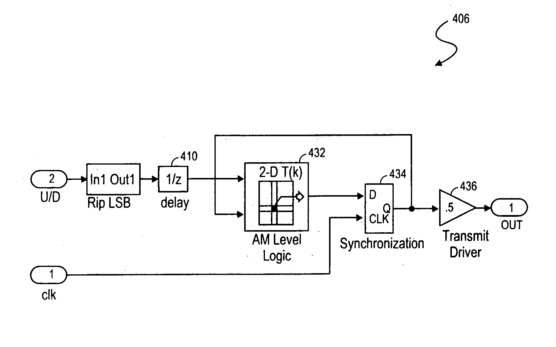
  • Method and apparatus to perform modulation using integer timing relationships between intra symbol modulation components
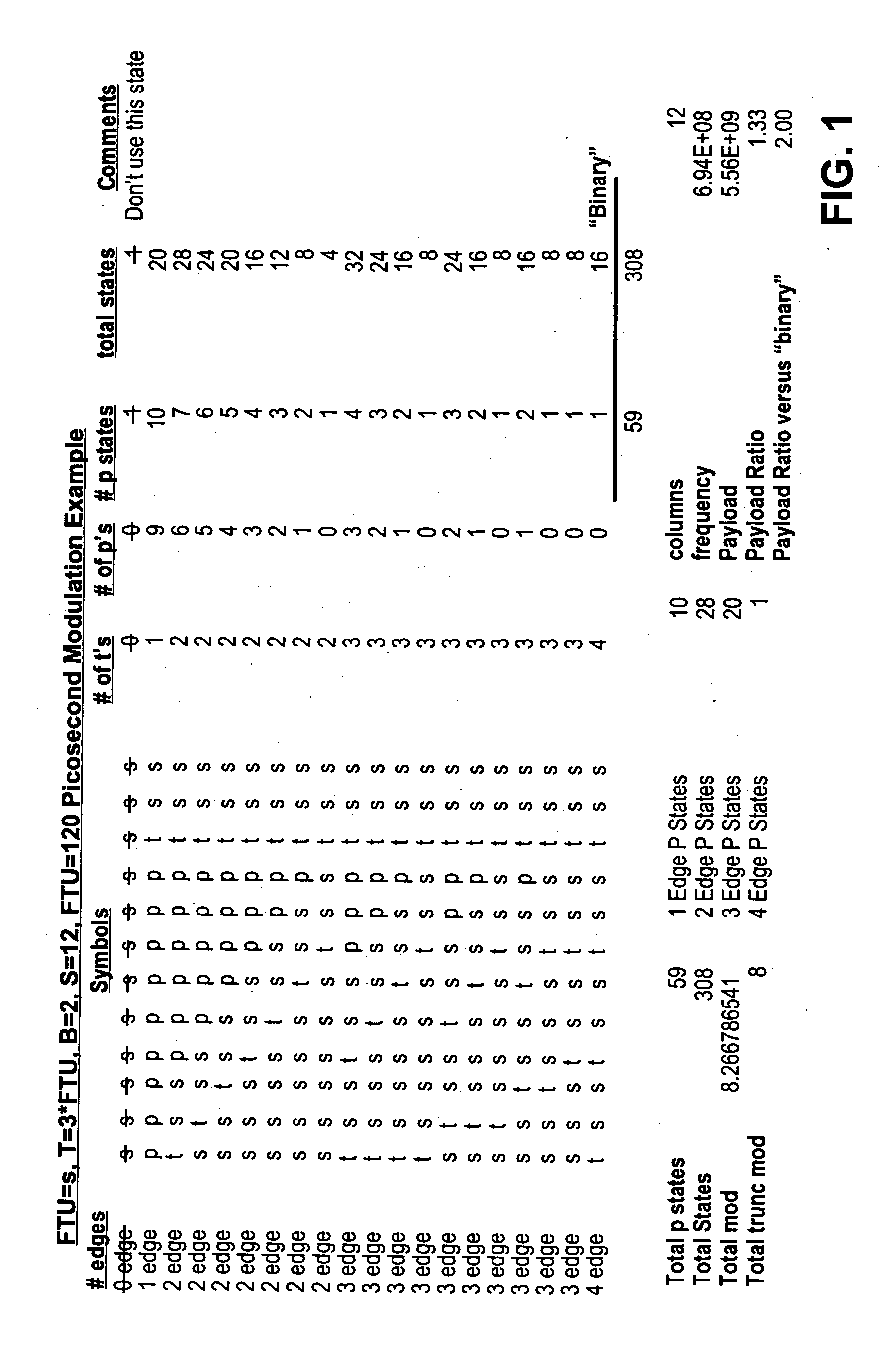
  • Method and apparatus to perform modulation using integer timing relationships between intra symbol modulation components
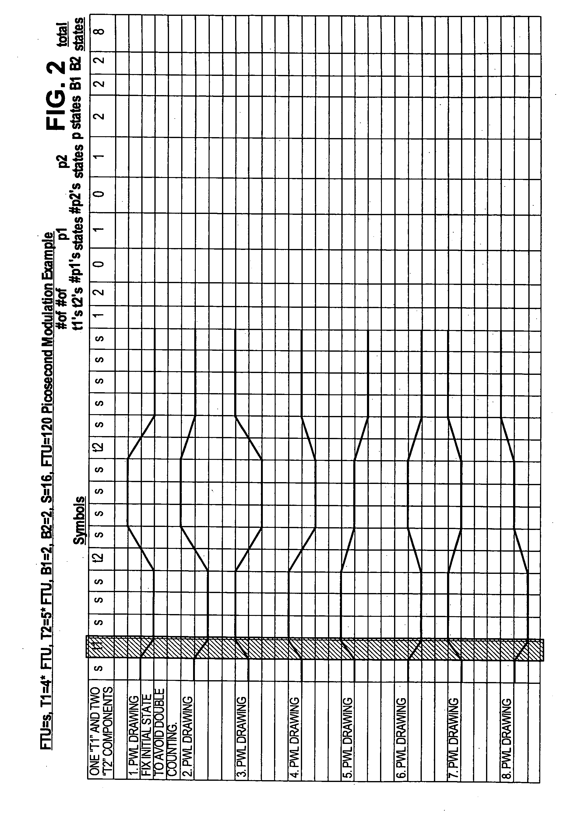
  • Method and apparatus to perform modulation using integer timing relationships between intra symbol modulation components

Examples


Embodiment Construction

[0017] One embodiment of the invention provides an improved modulation technique premised on multiples of a fundamental unit of time (FTU). Selection of the FTU size may be based on the minimum phase slot size for the system. In equalized channels, jitter and other noise factors over manufacturing variations become the limiting factor on slot size that can be resolved for a given bit error rate (BER). In this scheme, data is encoded in symbols in relation to the timing relationship of modulation objects within the symbol. In an embodiment, a symbol period (“S”) is an integer (“N”) multiple of the FTU. The symbol period may be selected in accordance with latency, complexity, and timing resolution possible with the timing constraints in the system employed. The delay lock loops (DLL), phase lock loops (PLL), delay elements, process employed, design of RF channel, manufacturing variations, and feature size all effect the desired symbol period.

[0018] In this description a phase slot fo...


PUM

PropertyMeasurementUnit
phaseaaaaaaaaaa
rise timeaaaaaaaaaa
timeaaaaaaaaaa

Abstract

A method and apparatus to improve modulation efficiency for chip to chip interconnects. Modulation objects that are integer multiples of a fundamental time unit (FTU) are used to populate a symbol period that is also an integer multiple of the FTU. A possible symbol set is established as the set in which the modulation object occupies every possible combination of slots within the symbol period. By permitting the modulation object to overlap positions in different symbols of the set, greater modulation efficiency is achieved.

Description

BACKGROUND [0001] 1. Field of the Invention [0002] Embodiments of the invention relate to modulation. More specifically, embodiments of the invention relate to an improved encoding density modulation scheme. [0003] 2. Description of the Related Art [0004] Various forms of modulation have long been used to encode data with greater efficiency so that more data can be transmitted during a particular time period over a transmission medium. Combinations of various modulation techniques such as, pulse width modulation, amplitude modulation and rise time modulation have been employed to improve the encoding density of modulation schemes. See for example, copending application entitled “Symbol-Based Signaling For An Electromagnetically-Coupled Bus System,” Ser. No. 09 / 714,244. However, such schemes typically employ a fixed base pulse residing in a fixed location within the symbol period. This can have a significant limiting effect on the possible modulation symbols available and therefore t...

Claims


Application Information

Patent Timeline
Patent Type & Authority Applications(United States)
IPC IPC(8): A61K8/00A61K8/02A61K8/06A61K8/72A61K8/81A61K8/87A61Q17/04A61Q19/00A61Q19/02A61Q19/04A61Q19/08A61Q19/10C08L33/06C08L75/04H04L5/12H04L25/49H04L25/493
CPCA61K8/8152A61K8/87A61K2800/5424A61K2800/594A61Q17/04A61Q19/00H04L25/493A61Q19/02A61Q19/04A61Q19/08A61Q19/10H04L25/4925A61Q19/004
Inventor TATE, LARRY R.
Owner INTEL CORP
Why Eureka
Try Eureka