Electro-optic modulator and preparation method thereof

An electro-optic modulator and electro-optic technology, applied in the fields of instruments, optics, nonlinear optics, etc., can solve the problems of low electro-optic modulation efficiency and large volume of electro-optic modulators

Active Publication Date: 2018-06-05
WUHAN POST & TELECOMM RES INST CO LTD
View PDF5 Cites 8 Cited by
  • Summary
  • Abstract
  • Description
  • Claims
  • Application Information

AI Technical Summary

Problems solved by technology

[0004] The purpose of the embodiments of the present invention is to provide an electro-optic modulator and its preparation me

Method used


Image

  • Electro-optic modulator and preparation method thereof
  • Electro-optic modulator and preparation method thereof
  • Electro-optic modulator and preparation method thereof

Examples


Embodiment Construction

[0020] In order to make the object, technical solution and advantages of the present invention more clear, the present invention will be further described in detail below in conjunction with the accompanying drawings and embodiments. It should be understood that the specific embodiments described here are only used to explain the present invention, not to limit the present invention.

[0021] In order to illustrate the technical solutions of the present invention, specific examples are used below to illustrate.

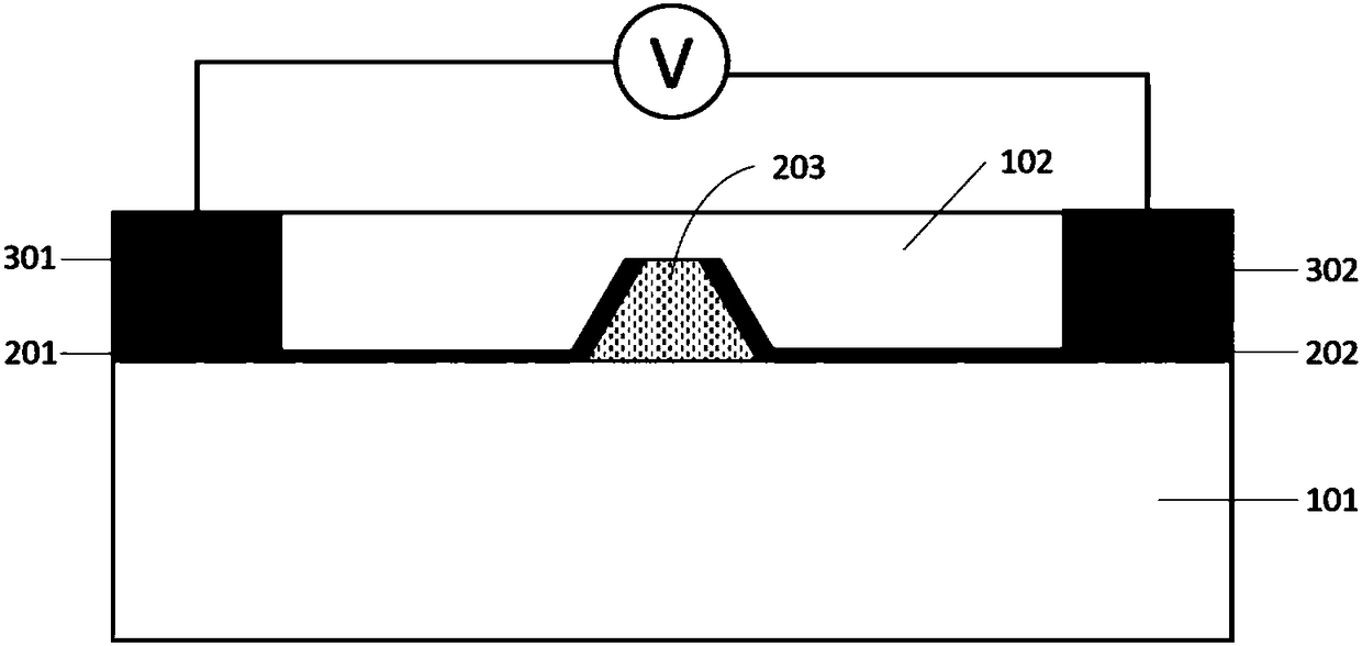
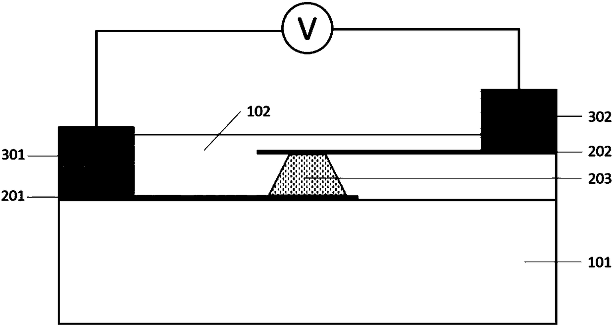
[0022] Such as Figure 1a , Figure 1b Shown is a structural diagram of an electro-optic modulator according to an exemplary embodiment of the present invention, and the electro-optic modulator includes:

[0023] Low refractive index substrate layer 101, the first graphene electrode 201, the second graphene electrode 202 formed on the substrate layer, the first metal electrode 301 formed on the first graphene electrode, formed on The second metal electrode 302 on th...


PUM


Abstract

The invention is applicable to an electro-optic modulator, and provides an electro-optic modulator and a preparation method thereof. The electro-optic modulator comprises a low refractive index substrate layer, a first graphene electrode, a second graphene electrode, a first metal electrode formed on the first graphene electrode, a second metal electrode formed on the second graphene electrode, ahigh electro-optic coefficient optical waveguide formed on the substrate layer and a low refractive index covering layer covering the high electro-optic coefficient optical waveguide, wherein the first graphene electrode and the second graphene electrode are formed on the substrate layer; and the first graphene electrode and the second graphene electrode are attached to the two sides of the high electro-optic coefficient optical waveguide respectively. By implementation of the electro-optic modulator, not only can the electro-optic modulator be miniaturized, but also the electro-optical modulation efficiency can be improved.

Description

technical field [0001] The invention belongs to the field of electro-optic modulators, in particular to an electro-optic modulator and a preparation method thereof. Background technique [0002] Due to its excellent properties, including high electro-optic response, high intrinsic bandwidth, wide transparent window (0.35um-5um) and good thermal stability, lithium niobate materials have been widely studied and applied in electro-optic modulators. However, because lithium niobate material is difficult to etch, the existing lithium niobate electro-optic modulator has a large structure size (generally about 10 cm), and it is difficult to realize the miniaturization and integration of the device. [0003] In order to reduce the size of the device and improve the performance of the modulator, the existing technology is to prepare optical waveguides by combining other high refractive index materials, such as silicon nitride, silicon, etc., or use lithium niobate to prepare optical ...

Claims


Application Information

Patent Timeline
IPC IPC(8): G02F1/03G02F1/035G02F1/065
CPCG02F1/0316G02F1/035G02F1/065
Inventor 张宇光胡晓肖希
Owner WUHAN POST & TELECOMM RES INST CO LTD
Why Eureka
Try Eureka