

Storage system executing encryption and decryption processing
- Summary
- Abstract
- Description
- Claims
- Application Information
AI Technical Summary
Benefits of technology
Problems solved by technology
Method used
Image

Examples
first embodiment
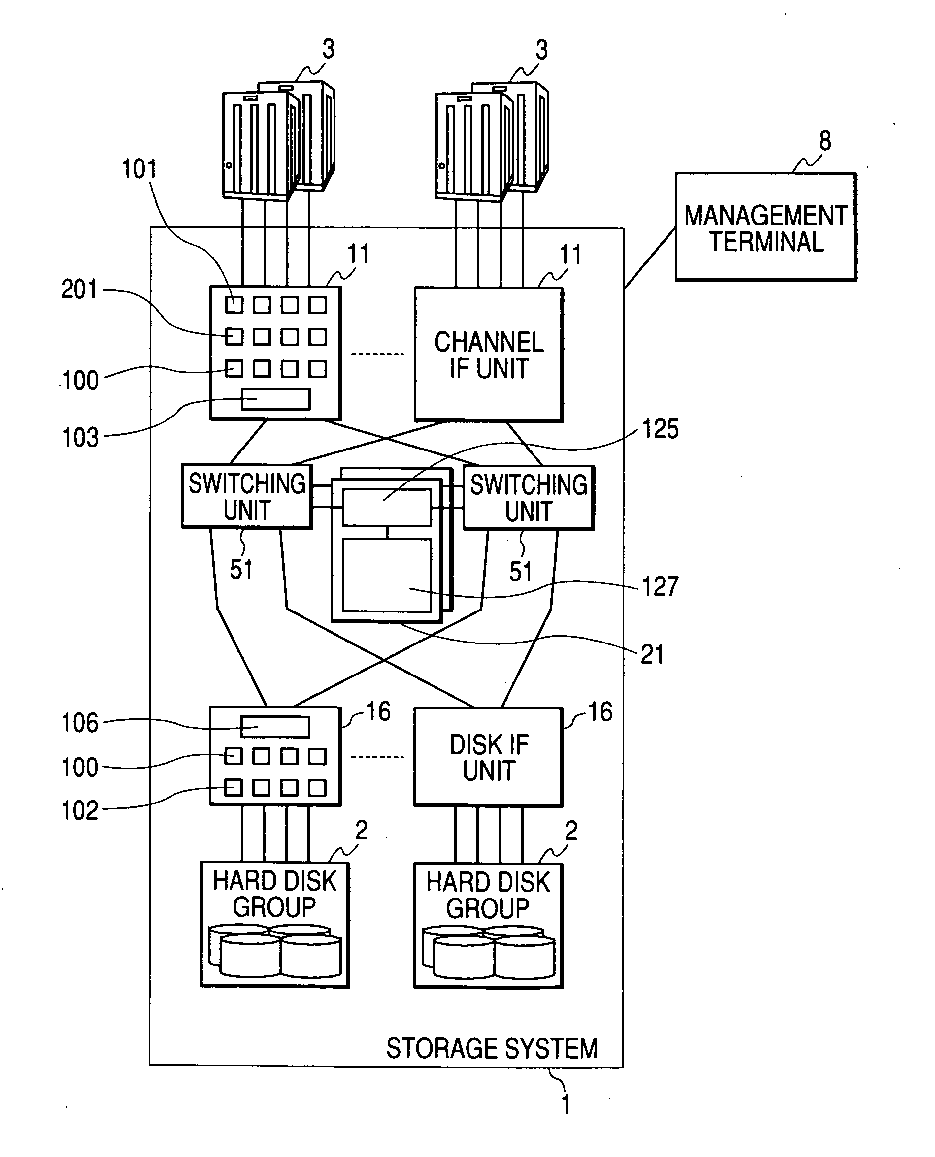
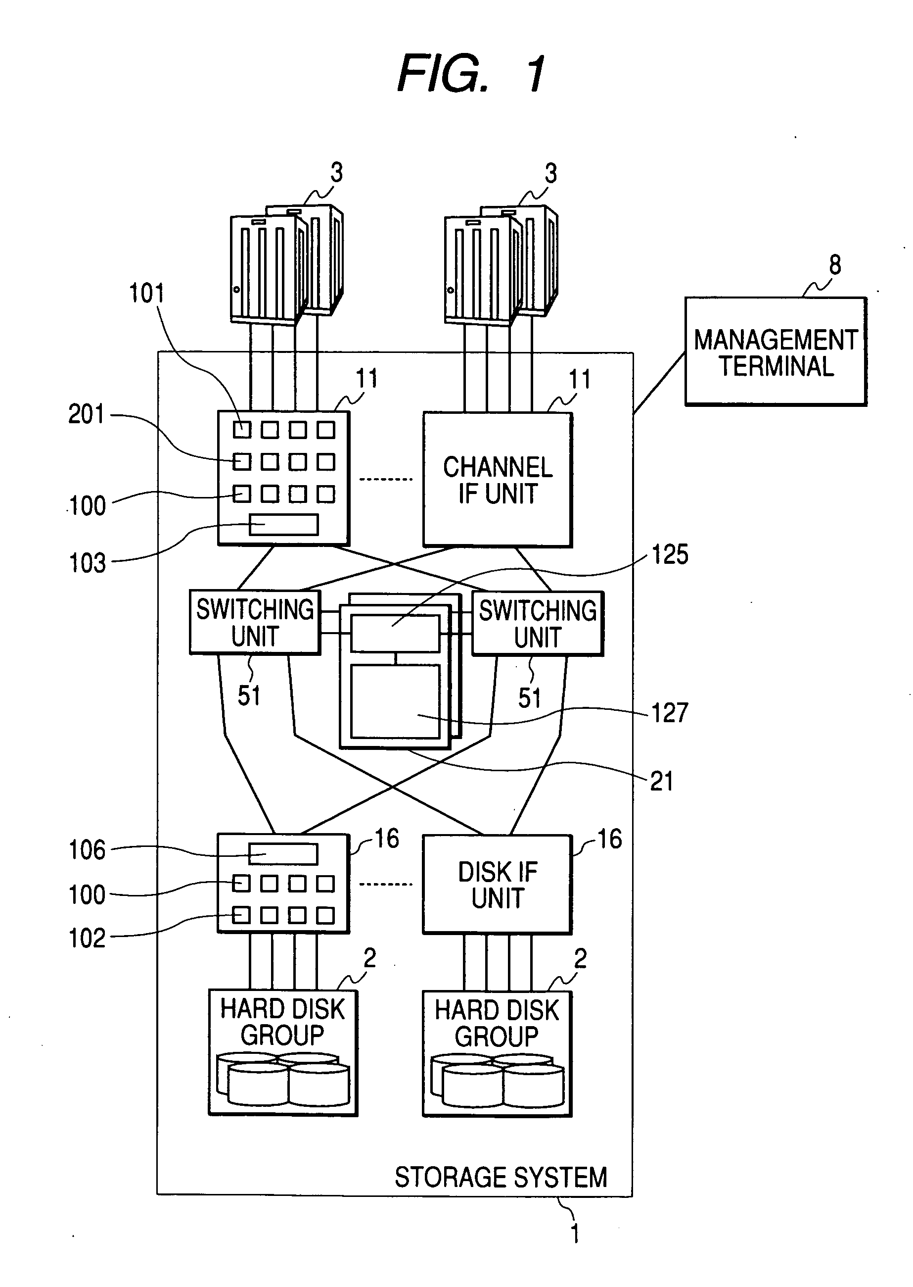
[0046]FIG. 1 is a block diagram illustrating the configuration of a system including a storage system according to the present invention. The system comprises a storage system 1 and servers 3. Hereinafter, it is assumed that an storage system 1 and the servers 3 are connected to each other through an IP network. However, networks other than the IP network, such as a FC network and the like, can be used. The storage system 1 is a storage apparatus comprising a plurality of recording media (a hard disk drive, an optical disk, a semiconductor memory, and the like) and a control unit. The storage system 1 has channel interface (IF) units 11 for transmitting or receiving data to or from the servers3, disk IF units 16 for transmitting or receiving data to or from hard disk groups 2, switching units 51, memory units 21, and the hard disk groups 2. The channel IF unit 11 and the disk IF unit 16 are connected to the memory unit 21 through the switching unit 51.
[0047] Further, a management te...
second embodiment
[0133]FIGS. 12 and 13 are views illustrating the configurations of a channel IF unit 11 respectively.
[0134] The configurations of the storage systems 1 shown in FIGS. 12 and 13 are the same as that shown in FIG. 1, except for the configuration of the channel IF unit 11. The configuration of the channel IF unit 11 according to the present embodiment is the same as that shown in FIG. 3, except that two encryption and decryption processing units are provided.
[0135] In the storage system 1 according to the present embodiment, similar to FIG. 3, the encryption and decryption processing unit 201 is provided in the transfer controller 103 (or the above-mentioned place), and an encryption and decryption processing unit 301 is provided in the front stage of the host IF 101 (the connecting portion between the host IF 101 and the IP network).
[0136] In the present embodiment, a high-speed cipher algorithm, for example, a stream cipher is used for a cipher algorithm of the encryption and decr...
third embodiment
[0153]FIGS. 16 and 17 illustrate configurations according to the
[0154] In the configuration of the storage system 1 shown in FIG. 16, the channel IF unit 11 and the disk IF unit 16 shown in FIG. 1 are integrated into one unit. That is, the disk IF 102 is connected to the transfer controller 103 of the channel IF unit 11 shown in FIG. 3 through the common bus 106. In addition, a memory module 131 serves as the cache memory and the control memory. Further, switches may be used instead of the common buses 104 and 106.
[0155]FIG. 17 is a view illustrating the configuration of a modification of the storage system shown in FIG. 16 in which two types of encryption and decryption processing units 201 and 301 are provided. In this case, similar to the second embodiment, the microprocessor 100 selects one of the encryption and decryption processing units 201 and 301 to perform the encryption and decryption processes according to the conditions previously determined by the management terminal,...
PUM
 Abstract
Description
Claims
Application Information