
Speaker for mobile terminals and manufacturing method thereof

a mobile terminal and speaker technology, applied in the direction of transducer details, geotextiles, constructions, etc., can solve the problems of difficult to reduce the size of both the speaker and the parts included in the speaker, difficult to produce a high quality sound pressure, and inability to achieve excellent sound quality, etc., to achieve excellent high frequency distortion characteristic, wide frequency characteristic, and compact structure

Inactive Publication Date: 2005-10-06
SAMSUNG ELECTRO MECHANICS CO LTD
View PDF2 Cites 69 Cited by
  • Summary
  • Abstract
  • Description
  • Claims
  • Application Information

AI Technical Summary

Benefits of technology

[0023] Accordingly, the present invention has been made keeping in mind the above problems occurring in the prior art, and an object of the present invention is to provide a speaker for mobile terminals which has a slim structure and has a wide frequency characteristic and an excellent high frequency distortion characteristic, thus accomplishing an excellent sound quality.
[0025] The diaphragm includes a first polymeric resin film, the plurality of voice coils comprising upper and lower voice coils respectively printed on upper and lower surfaces of the first polymeric resin film, and a second polymeric resin film to cover each of the upper and lower voice coils, thus preventing the upper and lower voice coils from corroding.
[0034] In order to accomplish the above object, the present invention provides a method of manufacturing a speaker for mobile terminals, which includes forming a frame to be integrated with a support plate which provides a magnetic circuit, attaching a first magnet vertically magnetized to an upper surface of the support plate and attaching a second magnet, magnetized in a direction opposite to a magnetic pole direction of the first magnet, to the upper surface of the support plate so that the second magnet is spaced apart from the first magnet at a predetermined interval, forming upper and lower voice coils on upper and lower surfaces of a first polymeric resin film to provide a multilayer and laminating second polymeric resin films to prevent corrosion of the upper and lower voice coils and insulate the upper and lower voice coils, thus forming a diaphragm, attaching the diaphragm to the frame so that an outer edge of the diaphragm is supported by an upper end of the frame, placing a protective plate on the frame to cover an open end of the frame, and welding input and output terminals of the upper and lower voice coils to a terminal piece of a printed circuit board (PCB).

Problems solved by technology

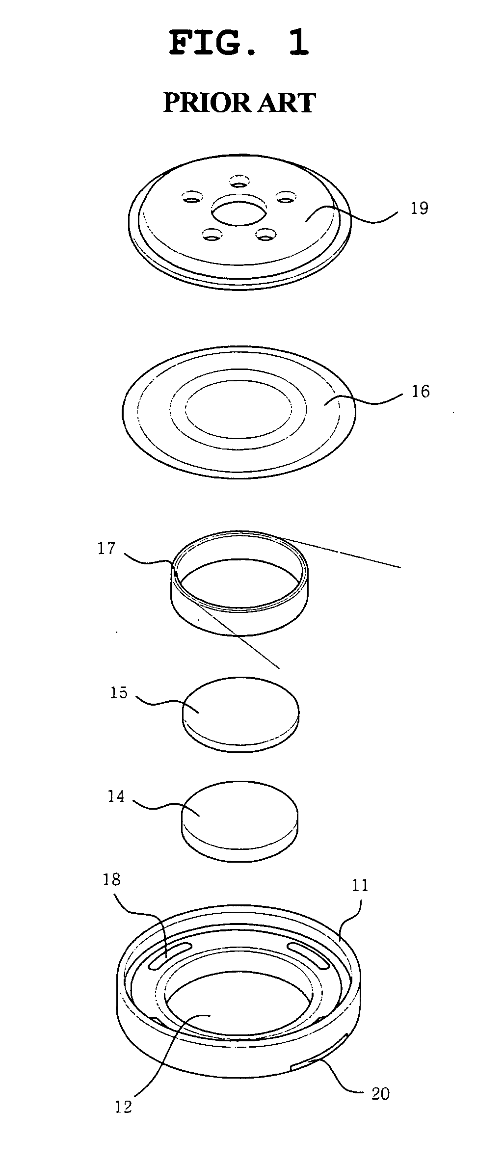
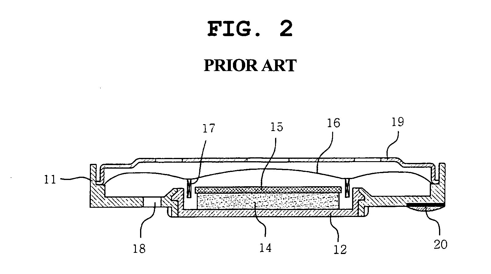
However, a conventional design technology has a problem in that it is difficult to reduce the size of both the speaker and the parts included in the speaker.
In this case, a sound pressure is reduced and thereby an excellent sound quality cannot be achieved.
However, the thin speaker has a problem in that the voice coil printed on the diaphragm is wound in the pattern of the eddy, in a direction from a terminal provided on an outer portion of the diaphragm to a center of the diaphragm, and then the voice coil is wound in a reverse direction, starting from the center of the diaphragm, so that a direction of a current flowing from the terminal to the center of the diaphragm is opposite to a direction of a current flowing from the center to the outer portion of the diaphragm, thus offsetting electromagnetic forces.
In such a thin speaker, a mutual magnetic interaction between the voice coil and a magnetic substance is weak, so that it is difficult to produce a high quality sound pressure.
Thus, efficiency of the speaker is deteriorated.
Particularly, in the case of adapting the speaker, having the voice coil printed on the diaphragm as described above, to a small appliance, such as the mobile terminal, efficiency of the speaker is low and a high quality reproduced sound is not achieved, because a diameter of the speaker is about 15 mm.

Method used


Image

  • Speaker for mobile terminals and manufacturing method thereof
  • Speaker for mobile terminals and manufacturing method thereof
  • Speaker for mobile terminals and manufacturing method thereof

Examples


first embodiment

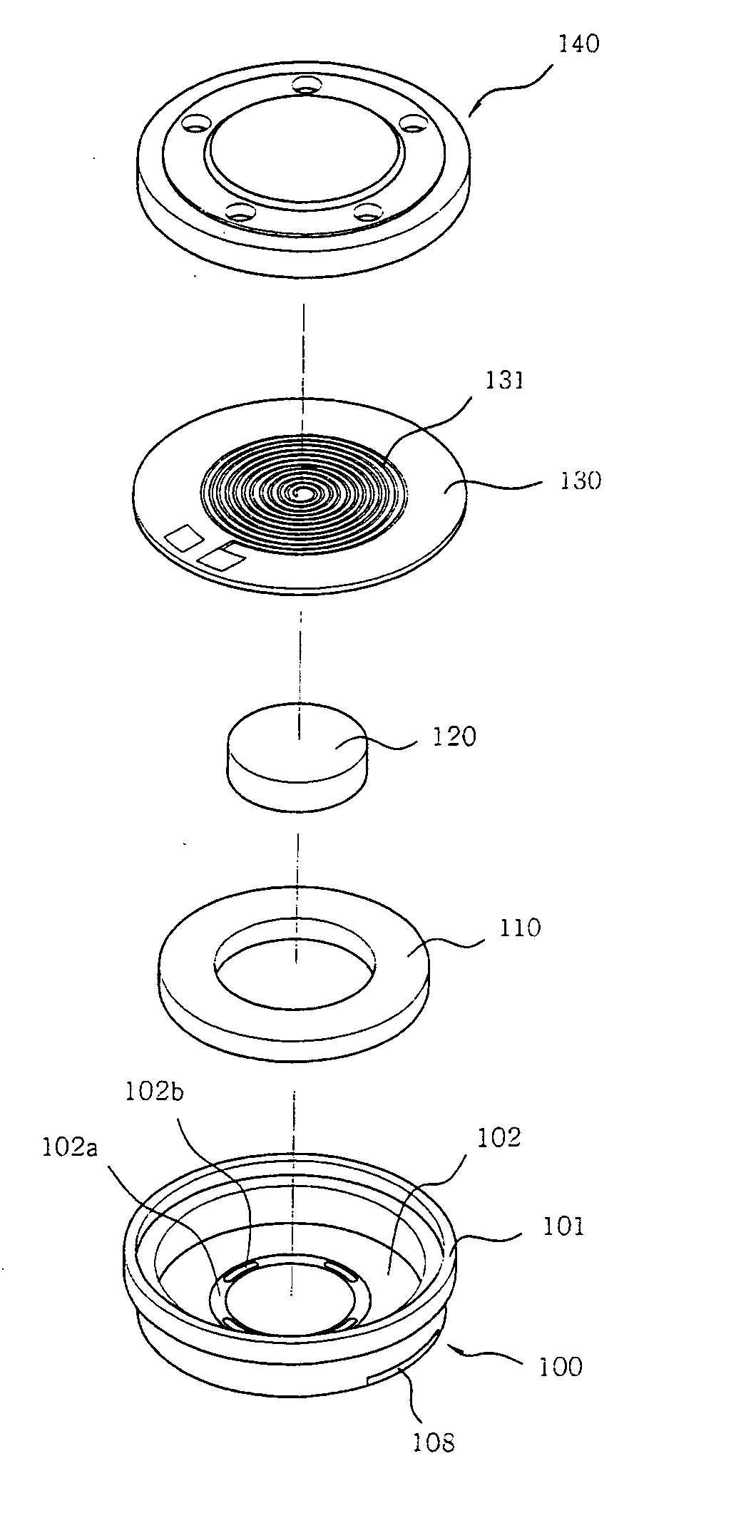
[0051] According to the present invention, the speaker for mobile terminals includes a frame 100, a support plate 102, a first magnet 120, a second magnet 110, a diaphragm 130, and a protective plate 140. The frame 100 defines a space therein, with a sidewall 101 extending upward from an outer edge of the frame 100 to a predetermined height. The support plate 102 is mounted to a lower end of the frame 100 to provide a magnetic circuit. The first magnet 120 is placed at a center of an upper surface of the support plate 102, and is magnetized in a vertical direction. The second magnet 110 is placed to surround the first magnet 120, and is magnetized in a vertical direction so that a magnetic pole direction of the second magnet 110 is opposite to that of the first magnet 120. The diaphragm 130 is provided at a position above the first and second magnets 120 and 110 to produce a sound. A plurality of voice coils 131 are integrally printed on the diaphragm 130 to form a multilayer, and g...

second embodiment

[0091]FIG. 8 is a perspective view to show a speaker for mobile terminals, according to this invention.

[0092] The speaker of the second embodiment includes a frame 200. A first support plate 202 is attached to a lower end of the frame 200 to provide a magnetic circuit. A first magnet 220 is placed at a center of an upper surface of the first support plate 202, and is magnetized vertically. An annular second magnet 210 is placed to surround the first magnet 220, and is magnetized vertically so that a magnetic pole direction of the second magnet 210 is opposite to a magnetic pole direction of the first magnet 220. Further, a diaphragm 230, which functions to produce a sound, is provided at a position above the first and second magnets 220 and 210. A plurality of voice coils 231 are integrally printed on the diaphragm 230 to form a multilayer, and generate a predetermined magnetic force. The speaker also has a protective plate 240 to cover an open end of the frame 200.

[0093] In the se...

third embodiment

[0107] a second support plate 350 is mounted to a lower surface of a protective plate 340 to provide a magnetic circuit. To a lower surface of the second support plate 350 are mounted a third magnet 360 and a fourth magnet 370. In this case, the third magnet 360 is magnetized vertically so that a magnetic pole direction of the third magnet 360 is opposite to a magnetic pole direction of the first magnet 320. The annular fourth magnet 370 surrounds the third magnet 360.

[0108] In this case, the fourth magnet 370 is magnetized so that a magnetic pole direction of the fourth magnet 370 is opposite to a magnetic pole direction of the third magnet 360.

[0109] In a detailed description, as shown in FIG. 10, when the first magnet 320 is magnetized so that a north pole is placed at an upper end of the first magnet 320 and a south pole is placed at a lower end of the first magnet 320, the second magnet 310 is magnetized so that a south pole is placed at an upper end of the second magnet 310 ...


PUM


Abstract

Disclosed herein are a speaker for mobile terminals which has a slim structure and has a wide frequency characteristic and an excellent high frequency distortion characteristic, thus accomplishing an excellent sound quality, and a method of manufacturing the speaker.

Description

BACKGROUND OF THE INVENTION [0001] 1. Field of the Invention [0002] The present invention relates generally to a speaker for mobile terminals and a method of manufacturing the same, and more particularly, to a speaker for mobile terminals which has a slim structure and has a wide frequency characteristic and an excellent high frequency distortion characteristic, thus accomplishing an,excellent sound quality, and to a method of manufacturing the speaker. [0003] 2. Description of the Related Art [0004] Recently, as a multimedia function has been rapidly supplied to a terminal for mobile telecommunications, an excellent sound quality has been accomplished. Further, as a thickness of a product is increasingly reduced, a space-economization type design with a thin frame is appealing. [0005] As a size of a window of a liquid crystal display (LCD) is increased, a space to accommodate a speaker serving as an exit of sound is reduced. Thus, there is required a development of a new speaker wh...

Claims


Application Information

Patent Timeline
IPC IPC(8): H04R9/00H04R1/00H04R9/02H04R9/04H04R9/06H04R11/06H04R31/00
CPCH04R9/047H04R9/025E02D3/12E02D29/0241E02D2250/003E02D2300/0085
Inventor KIM, KYUNG-TAELIM, JUN-WOOKIM, DEOK-RAEKIM, JI-WON
Owner SAMSUNG ELECTRO MECHANICS CO LTD
Learn More