
Method and apparatus for operating a fuel cell

Inactive Publication Date: 2005-10-06
WL GORE & ASSOC INC
View PDF5 Cites 22 Cited by
  • Summary
  • Abstract
  • Description
  • Claims
  • Application Information

AI Technical Summary

Benefits of technology

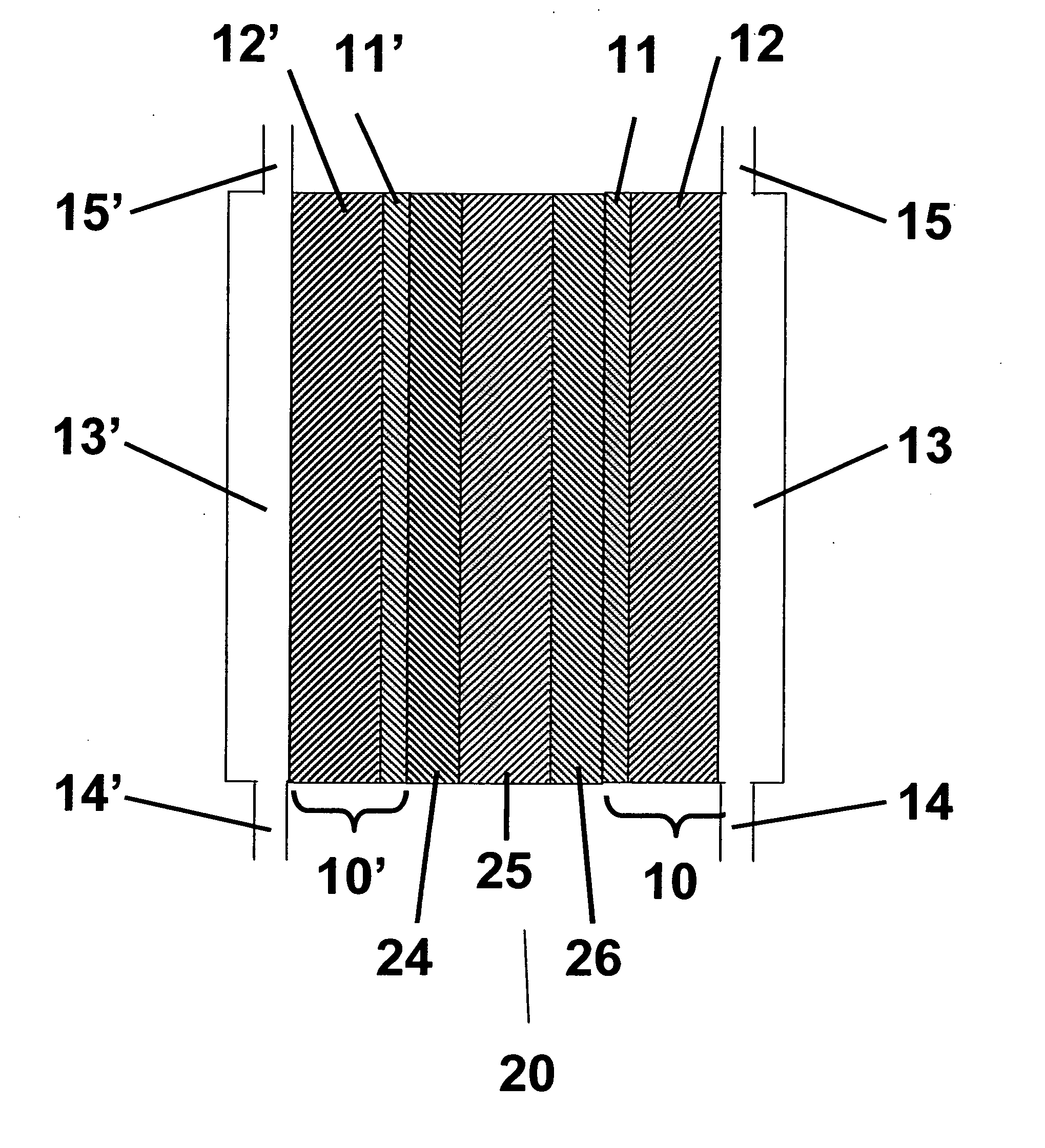
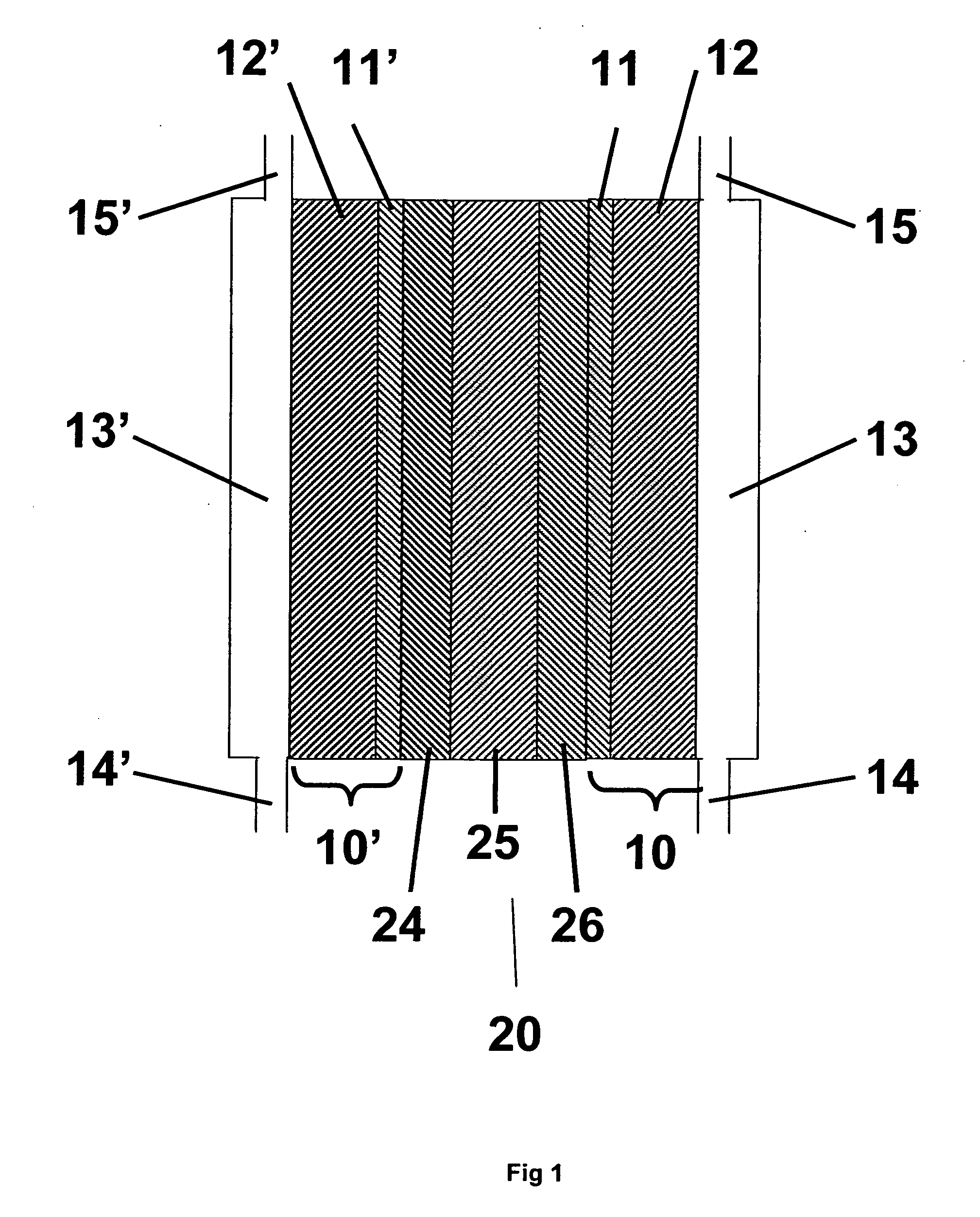
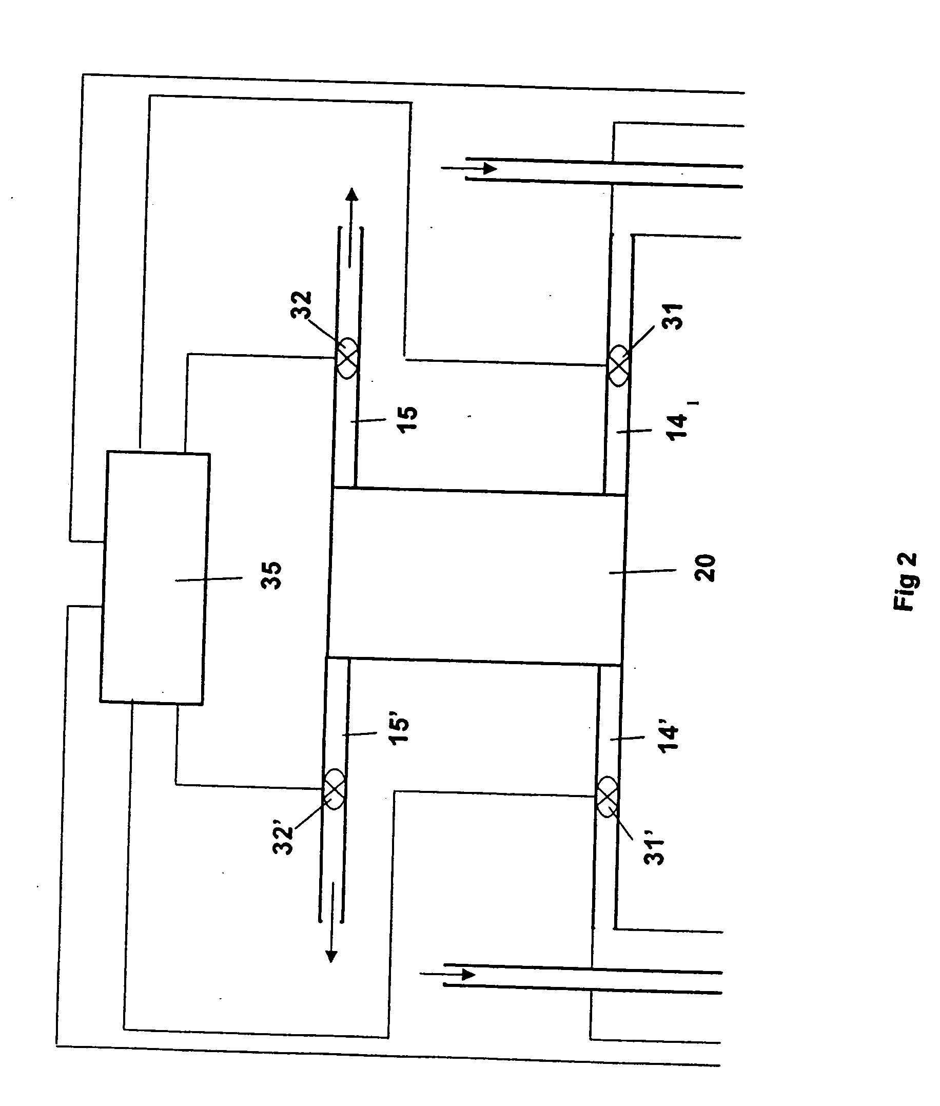
[0021]FIG. 2 is a schematic of an apparatus capable of operat

Problems solved by technology

As with any electrochemical device that operates using fluid reactants, unique challenges exist for achieving both high performance and long operating times. In order to achieve high performance it is necessary to reduce the electrical and ionic resistance of components within the device.
However, many technical challenges are still ahead.
However, reducing the membranes physical thickness can increase the susceptibility to damage from other device components leading to shorter cell lifetimes. Various improvements have been developed to mitigate this problem.
This decrease, described by various practitioners as voltage decay, fuel cell durability, or fuel cell stability, is not desirable because less useful work is obtained as the cell ages during use.
Ultimately, the cell or stack will eventually produce so little power that it is no longer useful at all.
In this application, the life tests are performed under constant current conditions, though it is well known in the art that constant voltage life tests will also produce decay in the power output of a cell.
Yet, with current materials and operating conditions lifetimes are unacceptably short at these higher temperatures.

Method used


Image

  • Method and apparatus for operating a fuel cell
  • Method and apparatus for operating a fuel cell
  • Method and apparatus for operating a fuel cell

Examples


examples

[0033] Description of Membrane Electrode Assemblies (MEAs) Three types of MEAs labeled Type A, Type B and Type C, were used in the testing. Type A MEAs were PRIMEA® Series 5510 Membrane Electrode Assemblies with a loading of 0.4 mg / cm2 Pt on both the anode and cathode sides, available from W. L. Gore & Associates. These MEAs comprise a GORE-SELECTcomposite membrane of an ePTFE-reinforced perfluorosulfonic acid ionomer. Type B MEAs were identical to Type A except there was an additional treatment to dope the membrane prior to assembly into an MEA with Fe at a level of about 550 ppm. Iron was chosen to be representative of catalysts capable of enhancing the formation of radicals from hydrogen peroxide that can accelerate membrane degradation. Specifically, iron was added to the membranes used in the preparation of Type A MEAs by preparing a 5 PPM iron solution by fully dissolving 0.034 g ferrous sulfate heptahydrate crystals in 1350 g deionized water. A weighed membrane of about 1.3 g...

examples 1-10

[0074] Cells were assembled and tested using the conditions shown in Table 1, where the average outlet relative humidity was sub-saturated. Temperatures were varied as shown between 80 and 130 degrees C. and the anode and cathode inlet RH together with the pressure was varied to assure that the outlet conditions were sub-saturated. In some cases, the stoichiometry of the anode gas, hydrogen, was adjusted as shown in Table 1 to maintain stable cell performance. Tests were performed using the three different types of MEAs and either bolt-loaded or spring-loaded cells as shown in Table 1. Results for these tests are shown in Table 2. At a given temperature, lifetimes are greater, average decay rate at two different currents are lower, and fluoride release rates are lower at the inventive conditions when compared to the Comparative Examples (Table 2, Examples 2-5 versus C1-C2). Extended lifetimes, low decay rates and reduced fluoride or proton release rates have been surprisingly observ...


PUM


Abstract

A method of operating a fuel cell at an operating temperature below about 150 degrees Celsius, wherein the fuel cell has an anode and a cathode with an electrolyte interposed therebetween, the cathode having at least one surface in contact with a cathode chamber having a gas inlet and a gas outlet, and the anode in contact with an anode chamber having a gas inlet and a gas outlet, and the electrolyte containing less than about 500 ppm of a catalyst capable of enhancing the formation of radicals from hydrogen peroxide. The method includes the steps of applying a fuel to the anode chamber; applying an oxidant to the cathode chamber; and controlling the amount of water supplied to the anode chamber and the cathode chamber such that water vapor pressure is sub-saturated at the operating temperature at the gas outlet of the cathode chamber. Also disclosed is an apparatus comprising sensors to measure outlet relative humidity of the gas outlets of a fuel cell and a means to control the relative humidity on the gas inlets of a fuel cell, such that the apparatus can control the relative humidity of the gas inlets to maintain an average relative humidity in the fuel cell of less than 100%.

Description

FIELD OF THE INVENTION [0001] The present invention relates to a method of operating a fuel cell or cells to improve their durability and life, and to an apparatus for doing so. BACKGROUND OF THE INVENTION [0002] Fuel cells are devices that convert fluid streams containing a fuel, for example hydrogen, and an oxidizing species, for example, oxygen or air, to electricity, heat and reaction products. Such devices comprise an anode, where the fuel is provided; a cathode, where the oxidizing species is provided; and an electrolyte separating the two. The fuel and / or oxidant typically is a liquid or gaseous material. The electrolyte is an electronic insulator that separates the fuel and oxidant. It provides an ionic pathway for the ions to move between the anode, where the ions are produced by reaction of the fuel, to the cathode, where they are used to produce the product. The electrons produced during formation of the ions are used in an external circuit, thus producing electricity. As...

Claims


Application Information

Patent Timeline
IPC IPC(8): H01M8/00H01M8/04H01M8/10
CPCH01M8/04119H01M8/1023H01M8/1025H01M8/1039H01M8/106H01M2300/0082H01M2300/0088Y02E60/50H01M8/04
Inventor LIU, WEN K.CLEGHORN, SIMON J.JOHNSON, WILLIAM B.
Owner WL GORE & ASSOC INC
Learn More