

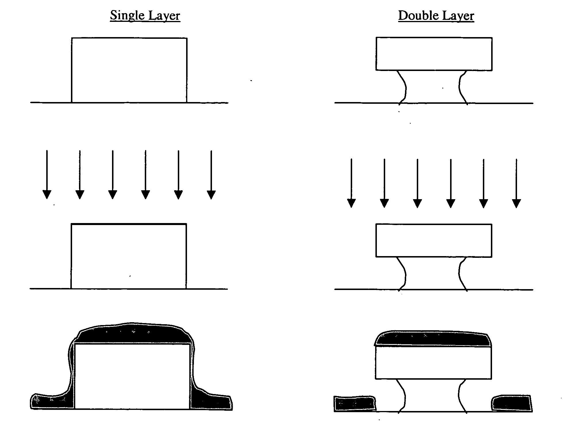
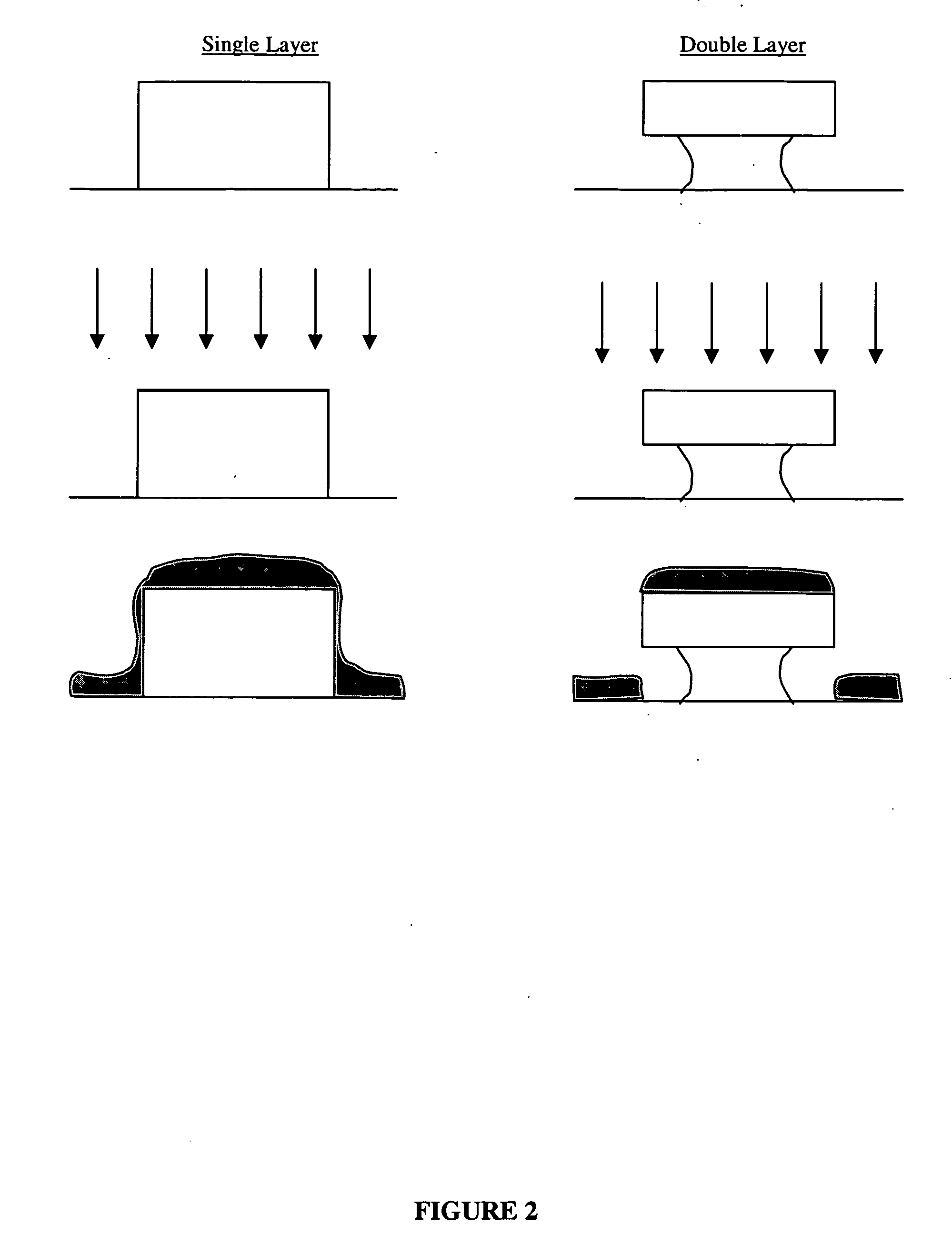
Method of forming a metal pattern on a substrate
a metal pattern and substrate technology, applied in the direction of double resist layers, photomechanical devices, instruments, etc., can solve the problems of potential lifting of unwanted resist patterns from the substrate, potential ragged lines of gold remaining after stripping, electrical shortening or near shortening, etc., to achieve a faster cure speed and cure to a higher cross link density
- Summary
- Abstract
- Description
- Claims
- Application Information
AI Technical Summary
Benefits of technology
Problems solved by technology
Method used
Image


Examples
example 1
for top resist
[0074]
Hydrophobic-fast cureTop LayerMaterialCAS #DryB2—57.228BPA(EO)DA41637-38-133.913NPAL15305-07-40.009MICKET90-94-80.101BENZO119-61-94.037BCIM1707-68-22.719PBCH87-84-30.770TBC77-94-10.933Crystal green633-03-40.036LEUCO548-62-90.255NPG103-01-50.360100.000
B2: 60,000 Mw; 110 Tg; A#110
example 2
for bottom resist
[0075]
Hydrophilic-slow cureBottom LayerMaterialCAS #DryB1—52.973TMP(EO)TA41637-38-138.400NPAL15305-07-40.020MICKET90-94-80.127BENZO119-61-94.225BCIM1707-68-21.024PBCH87-84-31.024TBC77-94-11.370crystal green633-03-40.009LEUCO548-62-90.829100.000
B1: 90,000 Mw; 110 Tg; A#145
[0076]
BPA (EO) DAExthoxylated Bis-phenol A diacrylateTMP (EO) TAExthoxylated trimethylolpropane triacrylateNPALTris(N-nitroso-N-phenylhydroxylamine)aluminum saltMicketMichler's ketoneBenzoBenzophenoneBCIM2,2 bis(2-chlorophenyl)-4,4-5,5-tetra phenyl-1,2biimidazolePBCHPentabromochloro cyclohexaneTBCTributyl CitrateLEYNCOLeuco crystal violetNPGN-phenylglycine
PUM
 Abstract
Description
Claims
Application Information