
Method and apparatus for measuring blood volume, and vital sign monitor using the same

Active Publication Date: 2005-10-06
NIHON KOHDEN CORP
View PDF2 Cites 49 Cited by
  • Summary
  • Abstract
  • Description
  • Claims
  • Application Information

AI Technical Summary

Benefits of technology

[0016] It is therefore an object of the invention to provide a blood volume measurement method, in which variation in the hemodynamics of a patient can be monitored invasively and continuously at all times, an aid of a skilled medical person in the insertion of a catheter or the like is not needed, suffering of the patient is lessened, and there is no risk of infection because it is non-invasive.
[0017] It is also an object of the invention to provide a blood volume measurement apparatus for embodying the above method with an inexpensive configuration.

Problems solved by technology

The thermodilution method involves a problem in that the measurement is intermittent and continuous measurements are not allowed.
Further, insertion of a catheter in the thermodilution method is highly invasive for a patient and involves a risk of infection and the like.
Recently, a method based on continuous measurements has also been developed in the thermodilution method, however, the method still requires insertion of a catheter, and the above-described problems in connection with the insertion of a catheter cannot be solved.
The dye dilution method also has a problem in that continuous measurements are impossible.
Further, the method requires a skilled medical person in the measuring process.
The ultrasound method imposes a burden of stress on a patient because a transducer is attached transesophageally.
Recently, a non-invasive measurement performed on the body surface has also been made available as a kind of the ultrasound method, but the continuous measurements are still impossible.
Considering the requirement for an aid of a medical person with advanced skill and the procedures being highly invasive for a patient, none of the methods described above can be conducted easily and continuously, and it is difficult to monitor the variation in the hemodynamics of a patient continuously at all times by these methods.

Method used


Image

  • Method and apparatus for measuring blood volume, and vital sign monitor using the same
  • Method and apparatus for measuring blood volume, and vital sign monitor using the same
  • Method and apparatus for measuring blood volume, and vital sign monitor using the same

Examples


Embodiment Construction

[0046] The principle used in the invention for the measurement of the blood volume ejected by cardiac contraction (cardiac output) will be explained below.

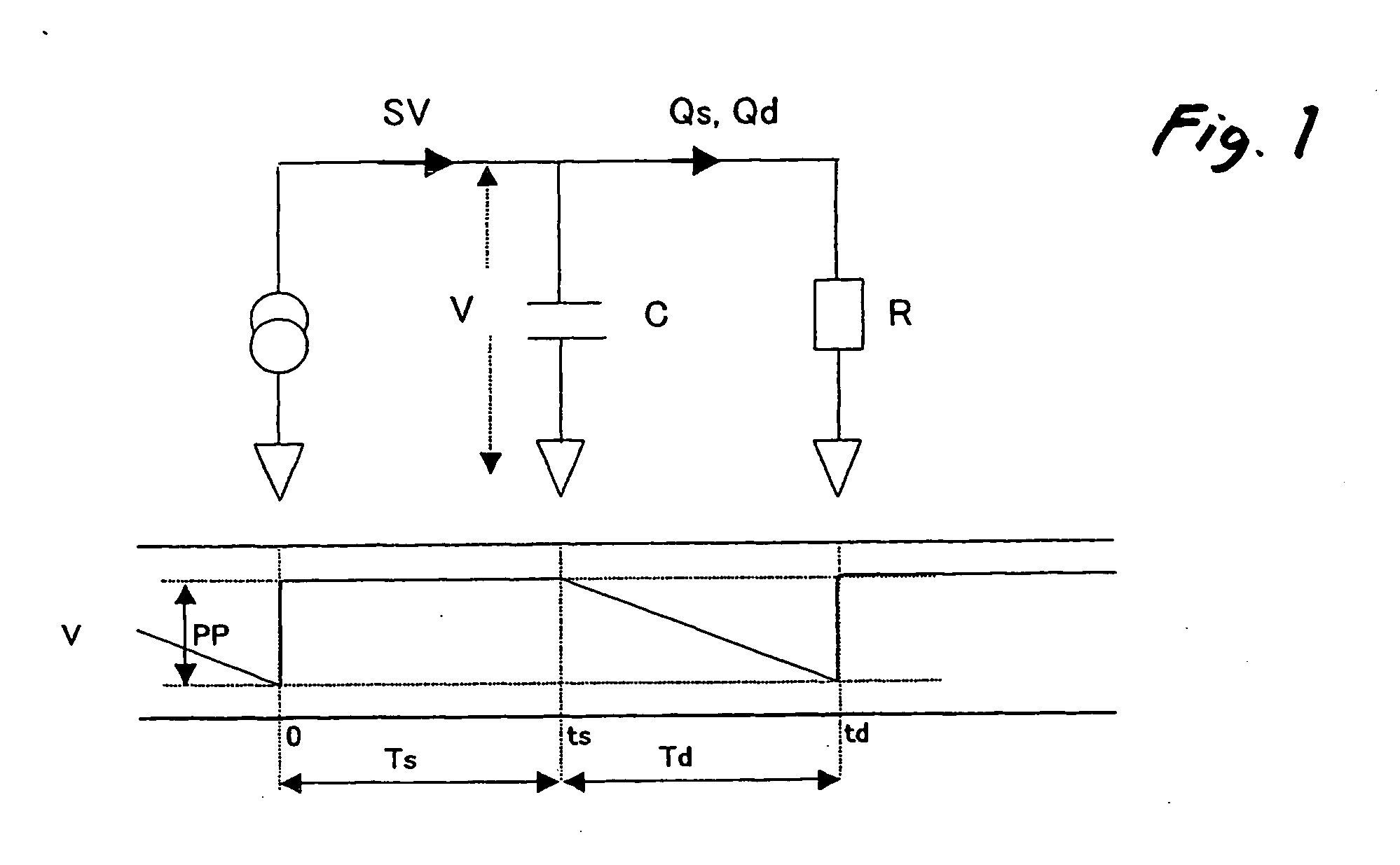
[0047] When the Windkessel model as shown in FIG. 1 is used, the influx flow volume to the aorta during a systole, that is, the flow volume (SV−Qs) obtained by deducting the efflux flow volume to the periphery during a systole Qs from the stroke volume SV, is represented by the product of the aortic compliance C with the pulse pressure PP (see Equation 1). In this specification, the term “pulse pressure” means a difference between the systolic blood pressure and the diastolic blood pressure.

SV−Qs=C·PP  (1)

[0048] The efflux flow volume to the periphery during a diastole Qd is the same as (SV−Qs). Further, Qs and Qd represent values obtained by dividing the systolic and diastolic arterial pressures V by the vascular resistance R and then multiplying by the systolic duration Ts and the diastolic duration Td, respectively. However,...


PUM


Abstract

A first member is adapted to measure an electrocardiogram of a patient. A second member is adapted to measure a peripheral pulse wave of the patient. A first calculator calculates a pulse wave propagation time (PWTT) and a heart rate (HR) of the patient based on the electrocardiogram and the peripheral pulse wave. A second calculator calculates a cardiac output (CO) of the patient with an equation of CO=(αK·PWTT+βK)·HR, where α, β and K are coefficients inherent to the patient.

Description

BACKGROUND OF THE INVENTION [0001] The present invention relates to a method and an apparatus for measuring blood volume ejected by cardiac contraction, and a vital sign monitor using such method and apparatus. [0002] In medical facilities, variation in the hemodynamics of a patient in an operating room, an intensive care unit (ICU), an emergency room, a dialysis treatment room or the like needs to be monitored continuously as long as possible. [0003] Conventionally, monitoring of the variation in the hemodynamics of such a patient has been predominantly carried out by direct monitoring of a blood pressure. [0004] In a living body, a cardiac output and a vascular resistance are regulated such that the blood pressure of the centrum is limited within a predetermined range. [0005] Therefore, in order to know the variation in the hemodynamics of a patient at an early stage, it is not enough to only monitor the blood pressure directly, and there is a need to know cause of change in the b...

Claims


Application Information

Patent Timeline
IPC IPC(8): A61B5/02A61B5/0245A61B5/0285A61B5/029A61B5/04
CPCA61B5/0245A61B5/0285A61B5/029
Inventor SUGO, YOSHIHIROAKIYAMA, TAKESHIUCHIDA, KEISUKETAKEDA, SUNAO
Owner NIHON KOHDEN CORP
Learn More